Diagram grids
Diagram grids provide you with a precise visual cue to identify the position and boundary of shapes in diagram editors. You can make use of diagram grid to improve the positioning and alignment of shapes, which makes the diagram looks more neat, tidy and impressive. By default, the grid lines are not visible. In this article, we will see how to show them and how to configure the various grid settings. We will use UML component diagram to explain the ideas but in practice, you can apply diagram grids on any diagram types - UML diagrams, BPMN diagrams, DFD, ERD etc.
Visibility of grid lines
Grid lines are not visible on diagrams by default. You can optionally show them by updating the grid settings. Here are the steps:
- Right click on the diagram where you want to show/hide grid lines.
- Select Open Specification... from the popup menu.
- Open the Grid Setting tab.
- Check/uncheck Grid visible and click OK.
Snap to grid
 |
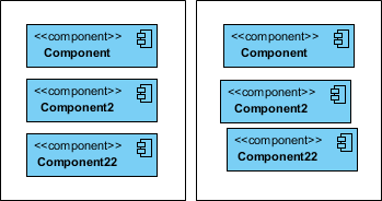
| Effect of snap-to-grid on and off (left and right hand side) |
The snap to grid function enables shapes to be positioned in an organized and well-aligned manner. When you draw, resize or move a shape on a diagram, it will align to the nearest grid line (even when grid lines are not visible). This means you can make multiple shapes apply to the same horizontal and/or vertical position, making the diagram looks more tidy. Note that the snap-to-grid option is turned on by default. If you want to change the setting:
- Right click on the diagram where you want to enable/disable snap-to-grid.
- Select Open Specification... from the popup menu.
- Open the Grid Setting tab.
- Check/uncheck Snap to grid and click OK.
Grid size
 |
| Different grid sizes - 5x5, 10x10 (default setting), 15x15 |
While the default spacing between grid line is set to 10 units, you can adjust the value to fulfill your diagramming needs. Please be reminded that when snap to grid is on, the shape you draw, resize or move will automatically align to the nearest grid line. This means that the value you input may influence the positioning of shapes. To update the grid size:
- Right click on the diagram where you want to change the grid size.
- Select Open Specification... from the popup menu.
- Open the Grid Setting tab.
- Edit the Width and Height of Grid size and click OK.
Grid color
 |
| Different grid colors - light gray (default setting), magenta, blue |
Grid lines are not visible on diagrams by default. If you set them visible, you can see the light gray lines on diagram. If you want to change the color of grid lines, take the follow steps:
- Right click on the diagram where you want to change the grid size.
- Select Open Specification... from the popup menu.
- Open the Grid Setting tab.
- Pick up a Grid color and click OK.
Related Articles
Related Links
Related Resources
The following resources may help you to learn more about the topic discussed in this page.
| 12. Zooming Diagram | Table of Contents | 14. Search bar |
