How to Draw State Machine Diagram?
State machine diagram is a kind of UML diagram that shows flow of control from state to state within single object. It usually contains simple states, composite states, composite states, transitions, events and actions.
Creating state machine diagram
Perform the steps below to create a UML state machine diagram in Visual Paradigm.
- Select Diagram > New from the application toolbar.
- In the New Diagram window, select State Machine Diagram.
- Click Next.
- Enter the diagram name and description. The Location field enables you to select a model to store the diagram.
- Click OK.
Creating states and transitions
After creating a state machine diagram, an initial pseudo state appears by default. You can create other states by using Resource Catalog:
- Move your mouse pointer over the source state.
- Press on the Resource Catalog button and drag it out.
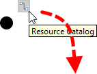
Using Resource Catalog - Release the mouse button at the place where you want the state to be created.
- Select the state to be created from Resource Catalog.
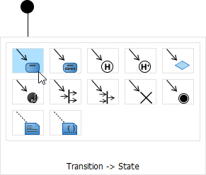
To create a state - A new state will be created and is transited from the source state. Enter its name and press Enter to confirm editing.

State created
Adding region to state
To model substates of a composite state, you need to add one or more regions to it. To add a region, right-click the state and select Add Horizontal Region from the popup menu.
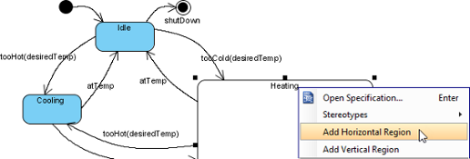 |
| Add region to state |
Next, you can draw the substates inside the region.
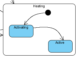 |
| Substates in a composite state |
Modeling properties of transition
To model properties of transition such as effect and guard, right-click the transition and select Open Specification... from the pop-up menu.
 |
| Open specification of transition |
When the Transition Specification pops out, you can edit its name, effect and guard. Next, select Create Activity... from the Effect property.
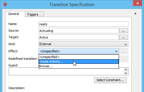 |
| Create Activity from transition |
In Activity Specification (Effect) window, change its name and then click OK button to apply the change.
Click OK in the Transition Specification to close it. The name and effect are shown on the transition caption.
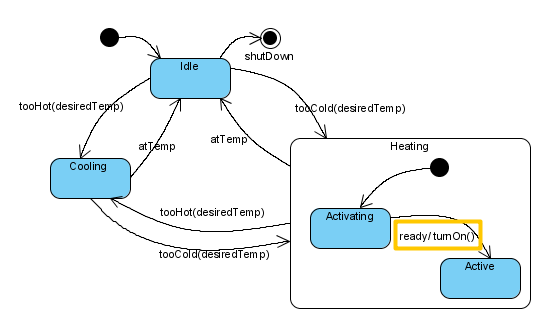 |
| Name and effect shown in caption of transition |
Related Resources
The following resources may help you to learn more about the topic discussed in this page.
- What is State Machine Diagram? - An introductory guide to State Machine Diagram
- New to Visual Paradigm? We have a lot of UML tutorials written to help you get started with Visual Paradigm
- Visual Paradigm on YouTube
- Visual Paradigm Know-How - Tips and tricks, Q&A, solutions to users' problems
- Contact us if you need any help or have any suggestion
| Chapter 5. State machine diagram | Table of Contents | Chapter 6. Activity diagram |
