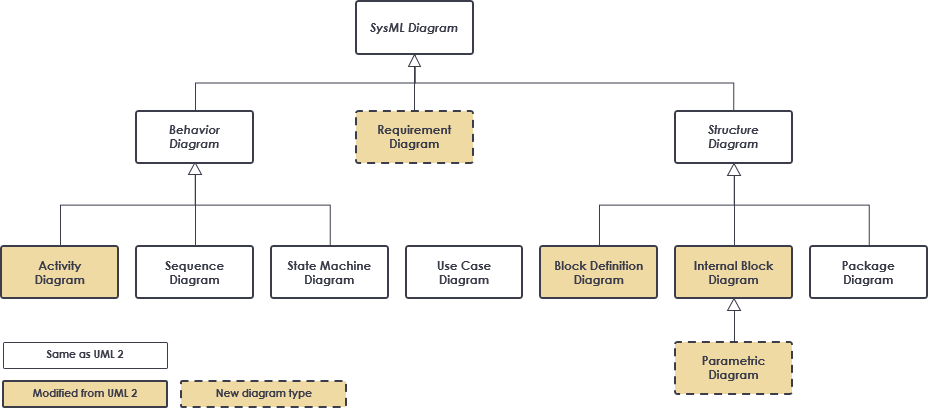
An activity diagram is a kind of behavior diagram; it’s a dynamic view of the system that expresses sequences of behaviors and event occurrences over time. In SysML, an activity diagram is inherited from UML with some minor modifications.
Activity diagrams, sequence diagrams, and state machine diagrams are the three options that SysML offers you to specify system behavior. All three can express sequential and concurrent behaviors and event occurrences over time. However, each one has strengths and weaknesses that make it more or less appropriate based on the needs of your target audience.
Activity diagrams can express complex control logic better than sequence diagrams and state machine diagrams. An activity diagram is particularly good at expressing the flow of objects—matter, energy, or data—through a behavior, with a focus on how the objects can be accessed and modified in the execution of that behavior during system operation. Thus, it is typically used to specify behavior, with a focus on the flow of control and the transformation of inputs into outputs through a sequence of actions. Common usages of an activity diagram in SysML includes:
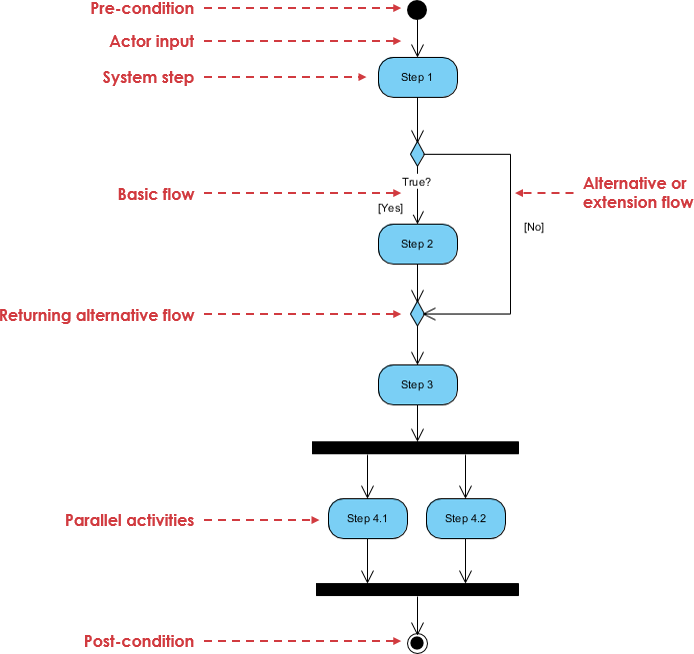
A basic activity diagram – flowchart like
| Notation Description | UML Notation |
| Activity
Is used to represent a set of actions |
 |
| Action
A task to be performed |
|
| Control Flow
Shows the sequence of execution |
|
| Object Flow
Show the flow of an object from one activity (or action) to another activity (or action). |
|
| Initial Node
Portrays the beginning of a set of actions or activities |
|
| Activity Final Node
Stop all control flows and object flows in an activity (or action) |
|
| Object Node
Represent an object that is connected to a set of Object Flows |
|
| Decision Node
Represent a test condition to ensure that the control flow or object flow only goes down one path |
 |
| Merge Node
Bring back together with different decision paths that were created using a decision-node. |
 |
| Fork Node
Split behavior into a set of parallel or concurrent flows of activities (or actions) |
 |
| Join Node
Bring back together with a set of parallel or concurrent flows of activities (or actions). |
 |
| Swimlane and Partition
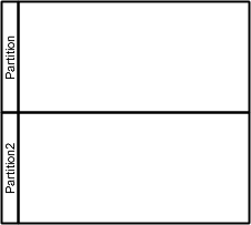
A way to group activities performed by the same actor on an activity diagram or to group activities in a single thread |
 |
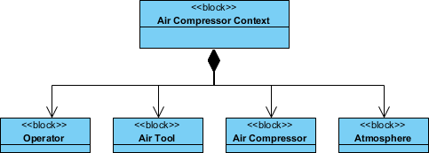
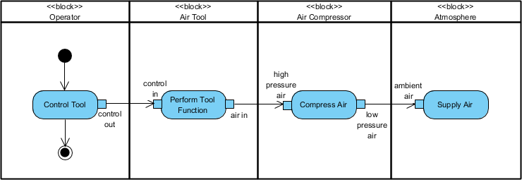
The figure below specifies how the Air Compressor interacts with the external systems, including the Air Tool, the Atmosphere, and indirectly with the Operator.
(*Source – Example extracted from – The Practical Guide to SysML 3rd ed by Morgan Kaufmann 2014)
The Block Definition Diagram includes a block called the Air Compressor Context that is composed of the Air Compressor and the entities that are external to the Air Compressor representing the user (Operator), external system (Air Tool), and the physical environment (Atmosphere).
The Air Compressor and the external systems are shown as activity partitions.
(*Source – Example extracted from – The Practical Guide to SysML 3rd ed by Morgan Kaufmann 2014)
The Compress Air action is further decomposed. Now, let’s continue the Air Compressor example, we can use an internal block diagram below to show how the components of the Air Compressor are interconnected.
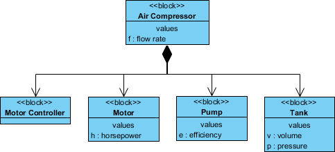
(*Source – Example extracted from – The Practical Guide to SysML 3rd ed by Morgan Kaufmann 2014)
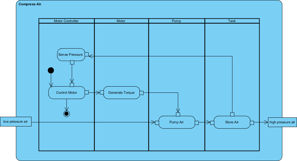
We can use the activity diagram to shows how the components interact within the Air Compressor when performing a compress Air action. The activity partitions in this activity diagram correspond to the four components of the air compressor as shown in the Swimlane Activity Diagram below:
(*Source – Example extracted from – The Practical Guide to SysML 3rd Ed by Morgan Kaufmann 2014)
The low-pressure air input and high-pressure air output are consistent with the input and output of the Compress Air action contained in the Behavior package along with the Operate Air Tool activity in the previous high-level activity diagram example.