A practical tutorial for architects and developers to bridge structural design with implementation using PlantUML, reverse engineering, and focused modeling.
Software architecture documentation often stalls at the Component level. Teams map out containers and components beautifully, but when developers open the IDE, they're left guessing: How is this actually implemented? Where do the business rules live? How do these classes interact?
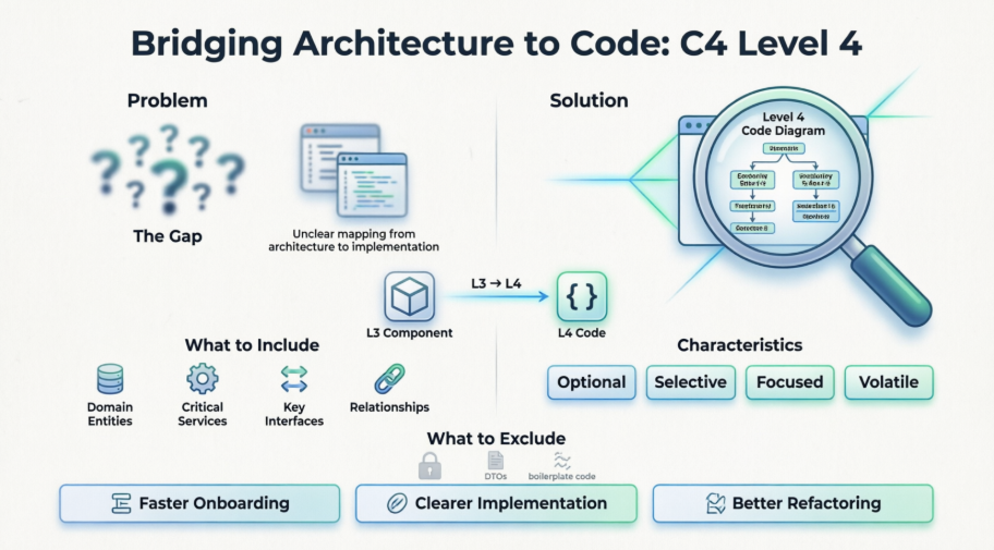
The C4 Model's Level 4 (Code Diagram) solves this gap. It zooms into a single component to reveal the actual code structure—typically as a UML Class diagram, though ER diagrams or interface maps are also valid.
Unlike Levels 1–3, Level 4 is optional, selective, and volatile. It's not meant to document every class or private method. Instead, it highlights the architecturally significant code: core domain entities, critical services, key interfaces, and the relationships that realize a component's responsibility.
✅ Complex business logic or domain models
✅ High-risk or frequently changing components
✅ Introducing new design patterns (CQRS, Strategy, Repository, DDD Aggregates)
✅ Technical discussions where class-level clarity prevents miscommunication
❌ Simple CRUD components, auto-generated DTOs, or utility classes
❌ Systems where the codebase is small and self-documenting
This tutorial walks you through a repeatable workflow in Visual Paradigm, provides ready-to-use PlantUML examples, and shares maintenance strategies to keep Level 4 diagrams valuable without becoming a documentation burden.
Before opening Visual Paradigm, internalize these rules to ensure your Level 4 diagrams stay useful:
| Principle | Why It Matters | How to Apply |
|---|---|---|
| Focus on Significance | L4 becomes unmaintainable if exhaustive | Show only classes/interfaces critical to the component's responsibility |
| Preserve Traceability | Architecture must link across levels | Keep the parent Component visible as a package/boundary |
| Limit Scope | Cognitive overload kills adoption | Target 5–15 classes maximum per diagram |
| Show Architectural Details Only | Implementation details change daily | Include key attributes/methods that reveal behavior or contracts |
| Prefer Generated Over Manual | Hand-drawn L4 diagrams rot quickly | Use reverse engineering; refine manually only for clarity |
| Tell a Story | Diagrams should answer "how does this work?" | Use notes, stereotypes, and directional relationships to explain flow |
💡 Rule of Thumb: If a class doesn't help a developer understand where to add a feature or why a dependency exists, leave it out.
Account Service, Payment Validator, Domain Model).🟢 Recommended: Sub-Diagram + Reverse Engineering
Create Sub-Diagram → UML Class Diagram.Tools > Code > Import Code🔵 Alternatives:
Diagram > New > UML > Class Diagram. Drag elements from Model Explorer for consistency."Generate a UML Class diagram for the AccountService component showing core entities, repositories, and gateway interfaces. Focus on public APIs and key dependencies."«Service», «Repository», «Entity», «Gateway» for quick scanning.───> Dependency───|> Generalization/Inheritance◆─── Composition○─── Aggregation..|> Realization (Interface)Arrange > Auto Layout, group by package/layer, minimize crossings.Container: API Application (Java + Spring Boot)
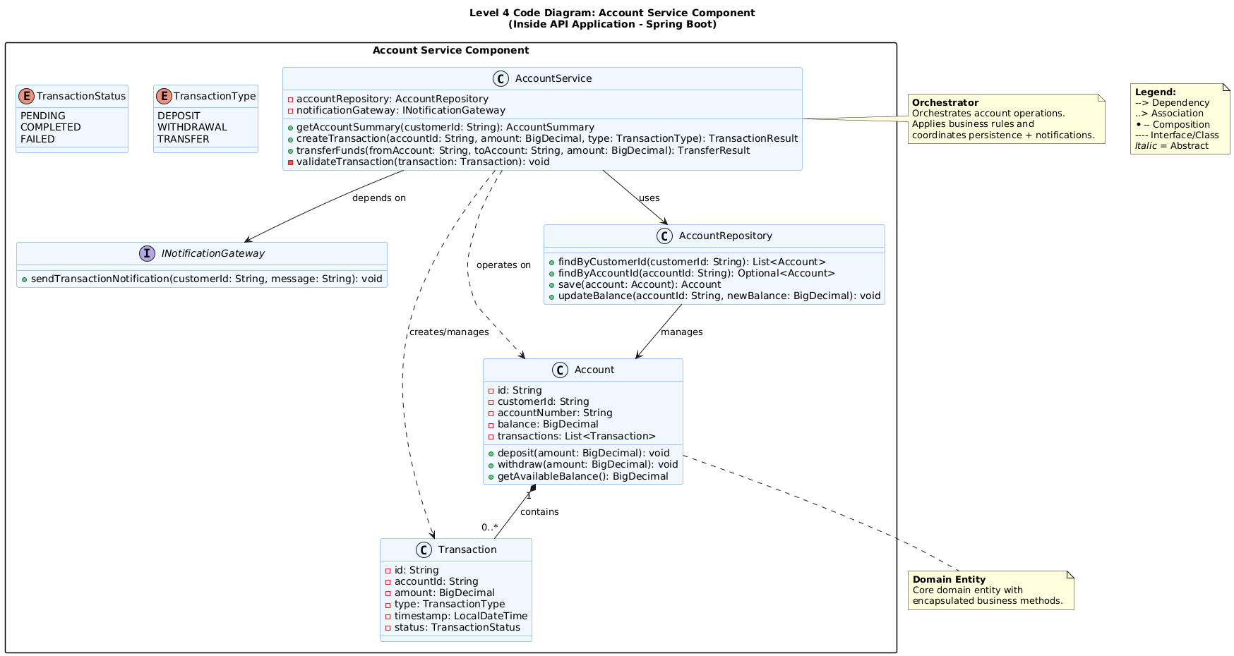
Component: Account Service (Orchestrates account operations, coordinates persistence & notifications)
Copy-paste this into Visual Paradigm's PlantUML editor, or any PlantUML renderer:
@startuml
title Level 4 Code Diagram: Account Service Component\n(Inside API Application - Spring Boot)
skinparam packageStyle rectangle
skinparam stereotypeCBackgroundColor #E8F4FD
skinparam classBackgroundColor #F0F7FF
skinparam classBorderColor #4A90D9
skinparam enumBackgroundColor #FFF4E6
skinparam enumBorderColor #FFA94D
package "Account Service Component" {
class AccountService {
- accountRepository: AccountRepository
- notificationGateway: INotificationGateway
+ getAccountSummary(customerId: String): AccountSummary
+ createTransaction(accountId: String, amount: BigDecimal, type: TransactionType): TransactionResult
+ transferFunds(fromAccount: String, toAccount: String, amount: BigDecimal): TransferResult
- validateTransaction(transaction: Transaction): void
}
interface INotificationGateway {
+ sendTransactionNotification(customerId: String, message: String): void
}
class AccountRepository {
+ findByCustomerId(customerId: String): List<Account>
+ findByAccountId(accountId: String): Optional<Account>
+ save(account: Account): Account
+ updateBalance(accountId: String, newBalance: BigDecimal): void
}
class Account {
- id: String
- customerId: String
- accountNumber: String
- balance: BigDecimal
- transactions: List<Transaction>
+ deposit(amount: BigDecimal): void
+ withdraw(amount: BigDecimal): void
+ getAvailableBalance(): BigDecimal
}
class Transaction {
- id: String
- accountId: String
- amount: BigDecimal
- type: TransactionType
- timestamp: LocalDateTime
- status: TransactionStatus
}
enum TransactionType {
DEPOSIT
WITHDRAWAL
TRANSFER
}
enum TransactionStatus {
PENDING
COMPLETED
FAILED
}
}
' Relationships
AccountService --> AccountRepository : uses
AccountService --> INotificationGateway : depends on
AccountService ..> Account : operates on
AccountService ..> Transaction : creates/manages
Account "1" *-- "0..*" Transaction : contains
AccountRepository --> Account : manages
note right of AccountService
<b>Orchestrator</b>
Orchestrates account operations.
Applies business rules and
coordinates persistence + notifications.
end note
note bottom of Account
<b>Domain Entity</b>
Core domain entity with
encapsulated business methods.
end note
' Optional: Manual legend instead of SHOW_LEGEND
note as Legend
<b>Legend:</b>
--> Dependency
..> Association
*-- Composition
---- Interface/Class
<i>Italic</i> = Abstract
end note
Diagram > New > PlantUML Diagram, paste the code, click Render.Convert to UML for full VP editing, layout tools, and model repository sync.Account Service component in your L3 diagram for automatic hierarchy navigation..puml file in your repo alongside code. Update when component contracts change.| Scenario | Recommended Approach |
|---|---|
| Starting from scratch | AI draft → Manual refinement → Reverse eng sync |
| Existing codebase | Reverse engineering → Filter packages → Add stereotypes/notes |
| Team collaboration | PlantUML in Git → VP for visual editing → Confluence embed |
| Behavioral context | Pair L4 Class diagram with Sequence/Activity diagrams for the same component |
| Large components | Split into multiple L4 diagrams: e.g., Domain Layer, Integration Layer, Validation Logic |
' Common C4/UML mappings for Level 4
AccountService --> AccountRepository       : "Dependency (uses)"
AccountRepository ..|> JpaRepository       : "Realization/Inheritance"
Account "1" *-- "0..*" Transaction         : "Composition (owns lifecycle)"
AccountService --> INotificationGateway    : "Interface dependency"
class Account #LightGreen                  : "Stereotype/Color for Domain"
note right of AccountService               : "Architectural intent"
Drilling from Component (Level 3) to Code (Level 4) completes the C4 hierarchy, transforming abstract architecture into actionable implementation guidance. When done right, Level 4 diagrams don't just document code—they enable precise technical conversations, accelerate onboarding, and prevent architectural drift.
🔹 Selective over exhaustive: Focus on architecturally significant classes, not every file.
Reverse engineering is your friend: Generate from code, then curate for clarity.
🔹 Traceability matters: Keep the parent Component visible to maintain the C4 thread.
🔹 PlantUML + Visual Paradigm = Hybrid power: Version-controlled code-friendly syntax with enterprise-grade visual modeling.
Pair structure with behavior: Class diagrams show "what exists"; Sequence/Activity diagrams show "how it works".
Level 4 diagrams are inherently volatile. Embrace that. Don't strive for perpetual perfection—strive for timely clarity. Generate them when the team needs them, validate them with the people who write the code, and update them when the architecture shifts.
"Architecture isn't just about drawing boundaries—it's about making the inside of those boundaries understandable."
With this workflow, your C4 documentation stops being a static artifact and becomes a living navigation system for your codebase. Start small. Stay focused. Let the code guide the diagram.
🔗 Resources:
Build clearly. Document intentionally. Ship confidently. ️✨