In today's fast-paced digital landscape, building robust, scalable, and secure software systems requires more than just writing code—it demands clear communication, shared understanding, and intentional design. Nowhere is this more critical than in the financial services sector, where systems must balance innovation with regulatory compliance, legacy integration, and unwavering reliability.
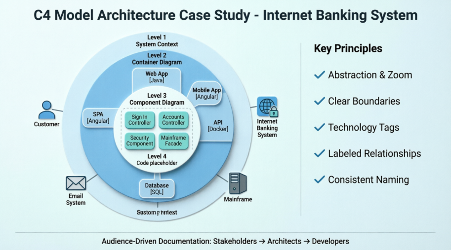
This case study explores the architectural design of a modern Internet Banking System through the lens of the C4 Model—a lightweight, hierarchical approach to visualizing software architecture. By documenting the system across four distinct levels of abstraction (Context, Containers, Components, and Code), we demonstrate how teams can bridge the gap between business stakeholders and technical implementers, ensuring everyone—from product managers to DevOps engineers—shares a common mental model of the system.
Whether you are an architect evaluating documentation frameworks, a developer seeking clarity on system boundaries, or a leader aiming to improve cross-functional alignment, this case study provides practical insights, reusable patterns, and actionable guidelines. We'll walk through a fictional but realistic banking scenario, illustrating how the C4 Model helps answer critical questions: What are we building? Who uses it? How does it connect to existing systems? And how is it structured internally?
By the end of this article, you'll have a clear understanding of how to apply the C4 Model to your own projects—and why investing time in thoughtful architectural visualization pays dividends in reduced ambiguity, faster onboarding, and more resilient systems.
This case study documents the architectural design of a new Internet Banking System for a fictional financial institution. The goal was to provide customers with a modern, multi-channel interface (Web and Mobile) to view account information and make payments, while integrating with a legacy Mainframe Banking System for core data storage.
The architecture was documented using the C4 Model, progressing from a high-level system context down to the internal components of the core API. This approach allowed stakeholders, developers, and operations teams to understand the system at the appropriate level of detail.
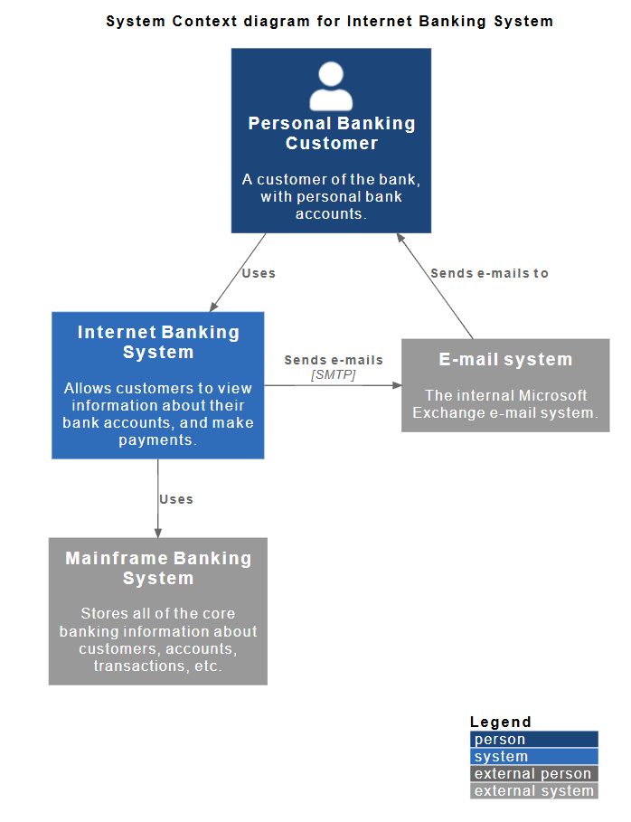
Audience: Non-technical stakeholders, business analysts, project managers.
Purpose: To show the system in the context of its users and external dependencies.
The diagram clearly defines the "System Boundary." Everything inside the blue box is what we are building; everything outside (Customer, Mainframe, Email) is outside our scope but necessary for operation.
@startuml
!include https://raw.githubusercontent.com/plantuml-stdlib/C4-PlantUML/master/C4_Context.puml
' uncomment the following line and comment the first to use locally
' !include C4_Context.puml
LAYOUT_WITH_LEGEND()
title System Context diagram for Internet Banking System
Person(customer, "Personal Banking Customer", "A customer of the bank, with personal bank accounts.")
System(banking_system, "Internet Banking System", "Allows customers to view information about their bank accounts, and make payments.")
System_Ext(mail_system, "E-mail system", "The internal Microsoft Exchange e-mail system.")
System_Ext(mainframe, "Mainframe Banking System", "Stores all of the core banking information about customers, accounts, transactions, etc.")
Rel(customer, banking_system, "Uses")
Rel_Back(customer, mail_system, "Sends e-mails to")
Rel_Neighbor(banking_system, mail_system, "Sends e-mails", "SMTP")
Rel(banking_system, mainframe, "Uses")
@enduml
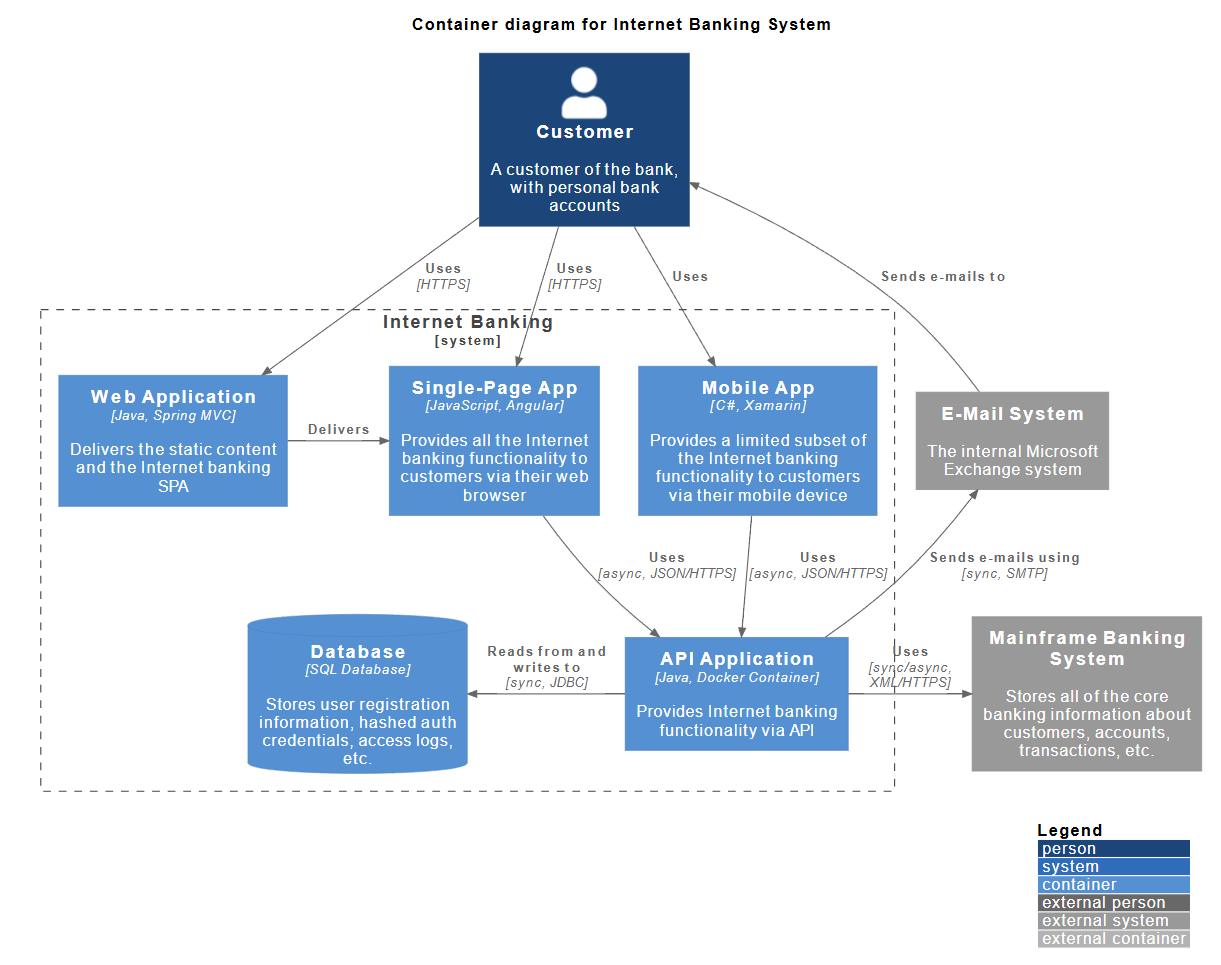
Audience: Software architects, developers, operations/support staff.
Purpose: To show the high-level technology choices and how the system is deployed.
The "Internet Banking System" from Level 1 is broken down into five distinct containers (deployable units):
@startuml
!include https://raw.githubusercontent.com/plantuml-stdlib/C4-PlantUML/master/C4_Container.puml
' uncomment the following line and comment the first to use locally
' !include C4_Container.puml
' LAYOUT_TOP_DOWN()
' LAYOUT_AS_SKETCH()
LAYOUT_WITH_LEGEND()
title Container diagram for Internet Banking System
Person(customer, Customer, "A customer of the bank, with personal bank accounts")
System_Boundary(c1, "Internet Banking") {
Container(web_app, "Web Application", "Java, Spring MVC", "Delivers the static content and the Internet banking SPA")
Container(spa, "Single-Page App", "JavaScript, Angular", "Provides all the Internet banking functionality to customers via their web browser")
Container(mobile_app, "Mobile App", "C#, Xamarin", "Provides a limited subset of the Internet banking functionality to customers via their mobile device")
ContainerDb(database, "Database", "SQL Database", "Stores user registration information, hashed auth credentials, access logs, etc.")
Container(backend_api, "API Application", "Java, Docker Container", "Provides Internet banking functionality via API")
}
System_Ext(email_system, "E-Mail System", "The internal Microsoft Exchange system")
System_Ext(banking_system, "Mainframe Banking System", "Stores all of the core banking information about customers, accounts, transactions, etc.")
Rel(customer, web_app, "Uses", "HTTPS")
Rel(customer, spa, "Uses", "HTTPS")
Rel(customer, mobile_app, "Uses")
Rel_Neighbor(web_app, spa, "Delivers")
Rel(spa, backend_api, "Uses", "async, JSON/HTTPS")
Rel(mobile_app, backend_api, "Uses", "async, JSON/HTTPS")
Rel_Back_Neighbor(database, backend_api, "Reads from and writes to", "sync, JDBC")
Rel_Back(customer, email_system, "Sends e-mails to")
Rel_Back(email_system, backend_api, "Sends e-mails using", "sync, SMTP")
Rel_Neighbor(backend_api, banking_system, "Uses", "sync/async, XML/HTTPS")
@enduml
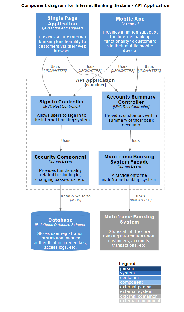
Audience: Software developers, software architects.
Purpose: To show how the "API Application" container is structured internally.
The API Application is decomposed into logical software components:
@startuml
!include https://raw.githubusercontent.com/plantuml-stdlib/C4-PlantUML/master/C4_Component.puml
' uncomment the following line and comment the first to use locally
' !include C4_Component.puml
LAYOUT_WITH_LEGEND()
title Component diagram for Internet Banking System - API Application
Container(spa, "Single Page Application", "javascript and angular", "Provides all the internet banking functionality to customers via their web browser.")
Container(ma, "Mobile App", "Xamarin", "Provides a limited subset ot the internet banking functionality to customers via their mobile mobile device.")
ContainerDb(db, "Database", "Relational Database Schema", "Stores user registration information, hashed authentication credentials, access logs, etc.")
System_Ext(mbs, "Mainframe Banking System", "Stores all of the core banking information about customers, accounts, transactions, etc.")
Container_Boundary(api, "API Application") {
Component(sign, "Sign In Controller", "MVC Rest Controller", "Allows users to sign in to the internet banking system")
Component(accounts, "Accounts Summary Controller", "MVC Rest Controller", "Provides customers with a summary of their bank accounts")
Component(security, "Security Component", "Spring Bean", "Provides functionality related to singing in, changing passwords, etc.")
Component(mbsfacade, "Mainframe Banking System Facade", "Spring Bean", "A facade onto the mainframe banking system.")
Rel(sign, security, "Uses")
Rel(accounts, mbsfacade, "Uses")
Rel(security, db, "Read & write to", "JDBC")
Rel(mbsfacade, mbs, "Uses", "XML/HTTPS")
}
Rel(spa, sign, "Uses", "JSON/HTTPS")
Rel(spa, accounts, "Uses", "JSON/HTTPS")
Rel(ma, sign, "Uses", "JSON/HTTPS")
Rel(ma, accounts, "Uses", "JSON/HTTPS")
@enduml
When a user requests an account summary via the Mobile App:
Based on this case study, here are the core principles of the C4 model applied in practice:
[Java, Spring MVC] or [SQL Database].Tip: In the Component diagram, the "API Application" is shown as a container boundary (dashed box) to reinforce that the components inside belong to that specific container.
The journey through this Internet Banking System case study underscores a fundamental truth: great software is built on great communication. The C4 Model isn't just a diagramming technique—it's a collaborative framework that transforms abstract requirements into shared understanding. By starting with the big picture (System Context) and progressively zooming into implementation details (Components and Code), teams can ensure that every stakeholder engages with the architecture at the right level of detail.
✅ Start with Why, Then How: The Context diagram aligns business and technical teams on scope and value before diving into technology choices.
✅ Boundaries Enable Autonomy: Clearly defined system and container boundaries empower teams to work independently while maintaining integration integrity.
✅ Technology Decisions Are First-Class Citizens: Explicitly documenting stacks, protocols, and data formats reduces ambiguity during implementation and operations.
✅ Relationships Tell the Story: Labeled connections (e.g., "async, JSON/HTTPS") convey critical integration contracts that diagrams alone cannot express.
✅ Consistency Builds Trust: Uniform naming and hierarchical decomposition prevent confusion and accelerate knowledge transfer across the organization.
Adopting the C4 Model is not about creating more documentation—it's about creating better documentation. In an era where systems grow increasingly distributed and complex, the ability to visualize, explain, and evolve architecture collaboratively is a competitive advantage. Whether you're modernizing a legacy banking platform or launching a greenfield product, the principles outlined here provide a scalable foundation for architectural excellence.
"If a picture is worth a thousand words, a well-structured set of C4 diagrams is worth a thousand meetings."
Use this case study as a template, adapt the patterns to your domain, and remember: the goal isn't perfect diagrams—it's clearer conversations, faster decisions, and software that delivers real value. 🚀