Based on the Internet Banking example, this guide breaks down the differences, key concepts, and best practices for using C4 Level 2 (Container) and Level 3 (Component) diagrams. These diagrams are part of the C4 model, a hierarchical approach to visualizing software architecture.
The C4 model helps you visualize software architecture at different levels of abstraction.
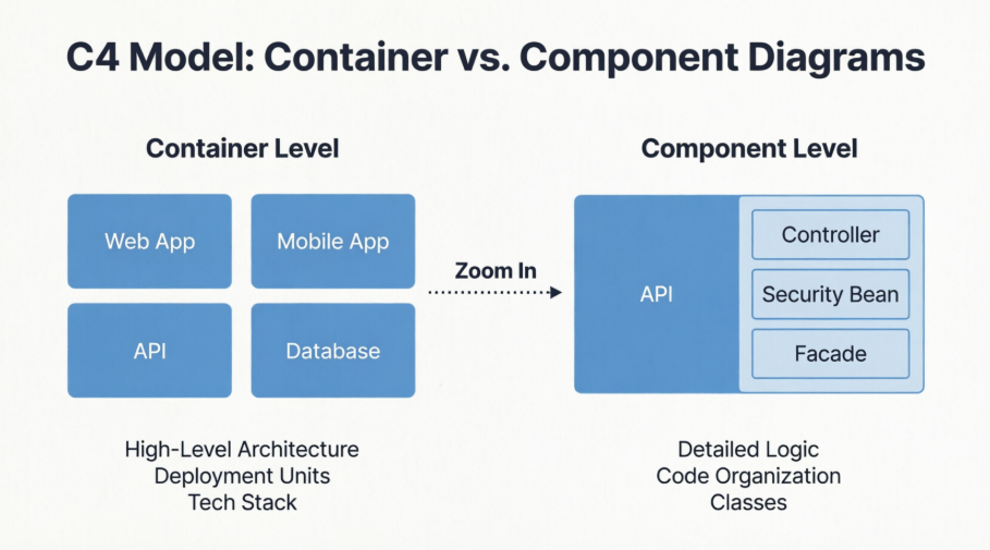
The Container Diagram: Represents Level 2. It zooms into the system to show the high-level technical building blocks (containers).
The Component Diagram: Represents Level 3. It zooms into a single container from the previous diagram to show its internal structure.
| Feature | Container Diagram (Image 1) | Component Diagram (Image 2) |
|---|---|---|
| Scope | The entire System (e.g., Internet Banking System). | A single Container (e.g., API Application). |
| Abstraction Level | High-level architecture. Shows "what" runs where. | Low-level design. Shows "how" the code is organized. |
| Primary Elements | Web Apps, Mobile Apps, Databases, Microservices, File Systems. | Controllers, Services, Repositories, Facades, Modules. |
| Technology Focus | Deployment/Runtime Tech: Java, .NET, Docker, SQL, Angular. | Framework/Code Structure: Spring Beans, MVC Controllers, Schemas. |
| Audience | Architects, Developers, Ops/DevOps, Business Stakeholders. | Developers, Software Architects. |
| External Dependencies | Shows external systems (e.g., Mainframe, E-Mail System). | Shows dependencies of the specific container (e.g., Database, Mainframe). |
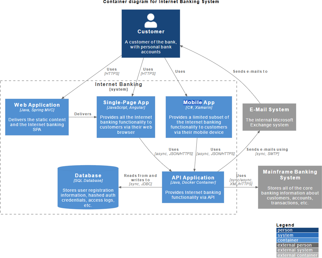
In C4, a "Container" is not just a Docker container. It is a separately runnable/deployable unit.
Examples from Image 1:
Web Application: A Java/Spring MVC app delivering static content.
Single-Page App: An Angular app running in the browser.
Database: An SQL Database storing user info.
API Application: A Java/Docker container providing backend logic.
Key Takeaway: If you have to deploy it separately or it runs in a separate process, it's a container.
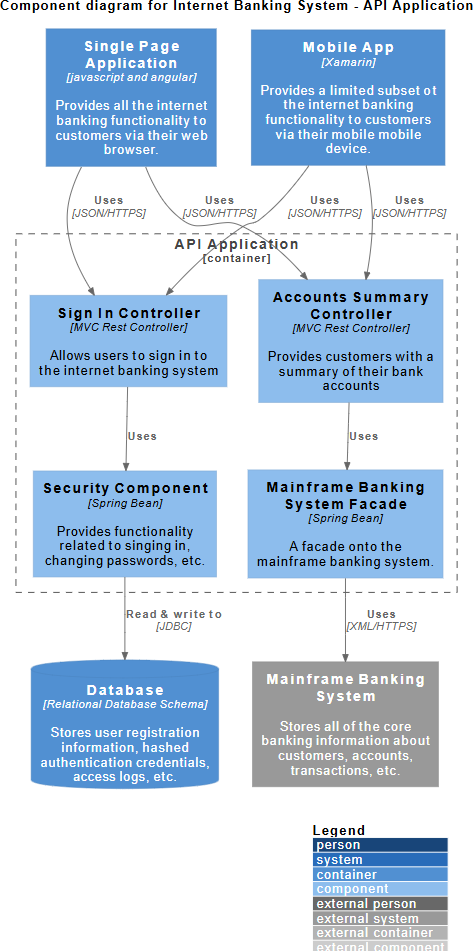
A "Component" is a grouping of related functionality inside a container. It is a logical code structure, not a deployment unit.
Examples from Image 2 (Inside the API Application):
Sign In Controller: Handles authentication requests.
Security Component: A Spring Bean handling passwords.
Mainframe Banking System Facade: A wrapper to talk to the external mainframe.
Key Takeaway: Components help explain how the code inside the "API Application" is organized without listing every single class file.
Include Technology Choices: Notice the text [Java, Spring MVC] or [C#, Xamarin]. This diagram is the perfect place to document what technologies are being used.
Show Communication Protocols: The arrows include details like [HTTPS], [async, JSON/HTTPS], and [sync, JDBC]. This is crucial for understanding how containers talk to each other (synchronous vs. asynchronous).
Define System Boundaries: Use the dashed line (as seen around "Internet Banking") to clearly separate your system from the outside world (like the "E-Mail System").
Don't Model Everything: You do not need a box for every class. Image 2 shows a healthy balance—it groups functionality into logical blocks like "Accounts Summary Controller" rather than listing GetAccount.java, PostAccount.java, etc.
Focus on "Interesting" Components: Only model components that are complex or important. Simple CRUD operations might not need a component diagram.
Show Internal Dependencies: Notice how the Sign In Controller uses the Security Component. This explains the flow of logic inside the application.
Map to External Dependencies: The Mainframe Banking System Facade connects to the external Mainframe Banking System. This shows how the internal code reaches out to the outside world.
Onboarding: You want to show a new developer or stakeholder the "big picture" of the system.
Tech Stack Decisions: You need to agree on which languages, databases, and frameworks the team will use.
Deployment Planning: You need to figure out how many servers/instances are needed (e.g., "We need a server for the Web App, one for the API, and a DB server").
Integration Analysis: You need to see how your system talks to third-party systems (like the Mainframe or E-Mail server).
Detailed Design: You are planning the code structure before writing it.
Refactoring: You are trying to untangle "spaghetti code" and need to visualize how modules depend on each other.
Documentation: You want to document specific parts of the codebase (like the API layer) for other developers.
Troubleshooting: You are trying to trace a bug and need to see which component handles which request (e.g., "Ah, the Sign In Controller calls the Security Component").
The relationship between these two diagrams is Zooming In.
Container Diagram gives you the Skeleton of the system. It tells you that the "Internet Banking System" is made of a Web App, a Mobile App, an API, and a Database. It establishes the technology stack.
Component Diagram gives you the Muscles of a specific part. It takes the "API Application" from Image 1 and opens it up to reveal that it is made of Controllers, Security Beans, and Facades.
Final Tip: Start with the Container diagram to get alignment on the architecture. Only drill down into Component diagrams for the containers that are complex or require detailed explanation. Not every container needs a component diagram!