1. Executive Summary
This case study documents the architectural design of a new Internet Banking System for a fictional financial institution. The goal was to provide customers with a modern, multi-channel interface (Web and Mobile) to view account information and make payments, while integrating with a legacy Mainframe Banking System for core data storage.
The architecture was documented using the C4 Model, progressing from a high-level system context down to the internal components of the core API. Additionally, a System Landscape Diagram was created to show the broader enterprise context. This comprehensive approach allowed stakeholders, developers, and operations teams to understand the system at the appropriate level of detail.
2. Supplementary Diagram: System Landscape Diagram
Audience: Enterprise architects, business stakeholders, IT strategy teams.
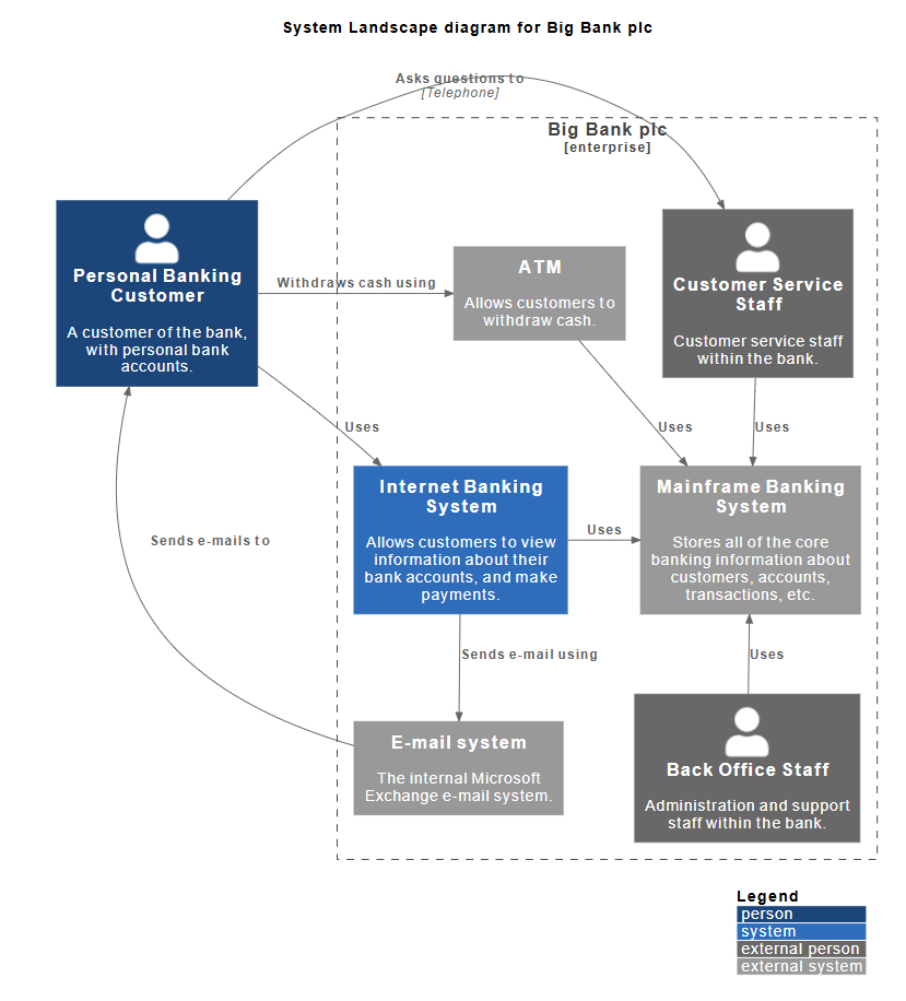
Purpose: To show how the Internet Banking System fits within the broader enterprise ecosystem of "Big Bank plc," including all people, systems, and their interactions.
Key Findings:
The System Landscape Diagram provides an enterprise-wide view that goes beyond a single system boundary:
- Enterprise Boundary: The dashed box labeled "Big Bank plc [enterprise]" encompasses all internal systems and staff.
- Multiple Actors:
- Personal Banking Customer (external) - The primary user of banking services.
- Customer Service Staff (internal) - Bank employees who assist customers.
- Back Office Staff (internal) - Administration and support staff.
- Multiple Systems:
- ATM - Allows customers to withdraw cash.
- Internet Banking System - Our focal system for digital banking.
- Mainframe Banking System - Core banking data repository.
- E-mail System - Internal Microsoft Exchange for communications.
Diagram Analysis:
Unlike the System Context diagram which focuses on a single system and its immediate dependencies, the Landscape diagram shows:
- Multiple interaction channels (ATM, Internet Banking, Customer Service)
- Internal staff roles and how they interact with systems
- The complete ecosystem of the enterprise
- How customers interact with the bank through multiple touchpoints
Relationships Mapped:
- Customer Interactions:
- Withdraws cash using → ATM
- Uses → Internet Banking System
- Sends e-mails to → E-mail System
- Asks questions to → Customer Service Staff (via Telephone)
- System Dependencies:
- Internet Banking System → Uses → Mainframe Banking System
- Internet Banking System → Sends e-mail using → E-mail System
- ATM → Uses → Mainframe Banking System
- Customer Service Staff → Uses → Mainframe Banking System
- Back Office Staff → Uses → Mainframe Banking System
- Staff Roles:
- Customer Service Staff supports customers and uses the mainframe
- Back Office Staff provides administrative support and uses the mainframe
PlantUML Code:
@startuml
!include https://raw.githubusercontent.com/plantuml-stdlib/C4-PlantUML/master/C4_Context.puml
LAYOUT_WITH_LEGEND()
title System Landscape diagram for Big Bank plc
Enterprise_Boundary(bank, "Big Bank plc") {
Person(customer, "Personal Banking Customer", "A customer of the bank, with personal bank accounts.")
System(atm, "ATM", "Allows customers to withdraw cash.")
System(internet_banking, "Internet Banking System", "Allows customers to view information about their bank accounts, and make payments.")
System(mainframe, "Mainframe Banking System", "Stores all of the core banking information about customers, accounts, transactions, etc.")
System(email, "E-mail system", "The internal Microsoft Exchange e-mail system.")
Person_Ext(customer_service, "Customer Service Staff", "Customer service staff within the bank.")
Person_Ext(back_office, "Back Office Staff", "Administration and support staff within the bank.")
}
Rel(customer, atm, "Withdraws cash using")
Rel(customer, internet_banking, "Uses")
Rel(customer, email, "Sends e-mails to")
Rel(customer, customer_service, "Asks questions to", "Telephone")
Rel(atm, mainframe, "Uses")
Rel(internet_banking, mainframe, "Uses")
Rel(internet_banking, email, "Sends e-mail using")
Rel(customer_service, mainframe, "Uses")
Rel(back_office, mainframe, "Uses")
SHOW_LEGEND(TRUE)
@enduml
3. Level 1: System Context Diagram
Audience: Non-technical stakeholders, business analysts, project managers.
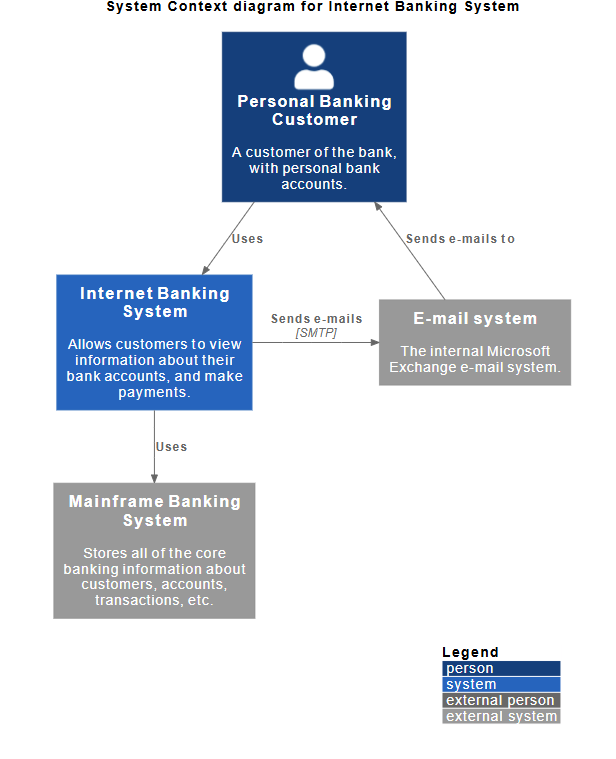
Purpose: To show the system in the context of its users and external dependencies.
Key Findings:
- The System: The Internet Banking System is the central focus. Its primary responsibility is allowing customers to view account info and make payments.
- Primary Actor: The Personal Banking Customer. They interact directly with the system.
- External Dependencies:
- Mainframe Banking System: A critical legacy system that stores all core banking data (customers, accounts, transactions). The Internet Banking System relies on this for data.
- E-mail System: An internal Microsoft Exchange system used to send notifications (e.g., password resets, transaction alerts) to the customer.
Diagram Analysis:
The diagram clearly defines the "System Boundary." Everything inside the blue box is what we are building; everything outside (Customer, Mainframe, Email) is outside our scope but necessary for operation.
PlantUML Code:
@startuml
!include https://raw.githubusercontent.com/plantuml-stdlib/C4-PlantUML/master/C4_Context.puml
' uncomment the following line and comment the first to use locally
' !include C4_Context.puml
LAYOUT_WITH_LEGEND()
title System Context diagram for Internet Banking System
Person(customer, "Personal Banking Customer", "A customer of the bank, with personal bank accounts.")
System(banking_system, "Internet Banking System", "Allows customers to view information about their bank accounts, and make payments.")
System_Ext(mail_system, "E-mail system", "The internal Microsoft Exchange e-mail system.")
System_Ext(mainframe, "Mainframe Banking System", "Stores all of the core banking information about customers, accounts, transactions, etc.")
Rel(customer, banking_system, "Uses")
Rel_Back(customer, mail_system, "Sends e-mails to")
Rel_Neighbor(banking_system, mail_system, "Sends e-mails", "SMTP")
Rel(banking_system, mainframe, "Uses")
@enduml
4. Level 2: Container Diagram
Audience: Software architects, developers, operations/support staff.
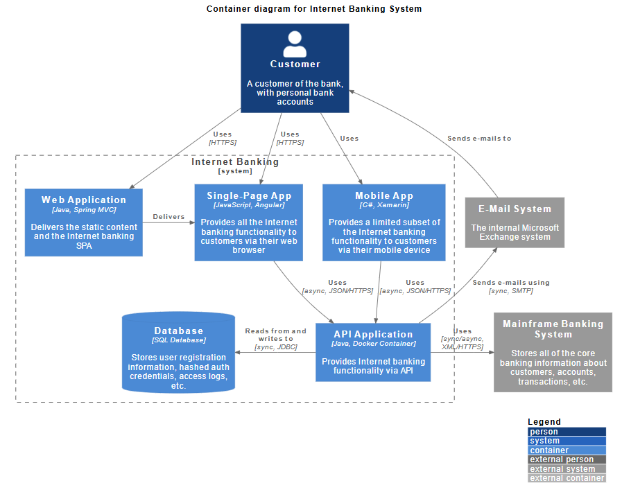
Purpose: To show the high-level technology choices and how the system is deployed.
Key Findings:
The "Internet Banking System" from Level 1 is broken down into five distinct containers (deployable units):
- Web Application:
- Tech: Java, Spring MVC.
- Role: Delivers static content and hosts the Single-Page Application (SPA).
- Single-Page App (SPA):
- Tech: JavaScript, Angular.
- Role: Runs in the user's browser, providing the full internet banking functionality.
- Mobile App:
- Tech: C#, Xamarin.
- Role: Provides a limited subset of functionality for mobile users.
- API Application:
- Tech: Java, Docker Container.
- Role: The core backend logic. It provides internet banking functionality via an API to both the Web SPA and the Mobile App.
- Database:
- Tech: SQL Database.
- Role: Stores user registration, hashed credentials, and access logs (separate from the core banking data in the Mainframe).
PlantUML Code:
@startuml
!include https://raw.githubusercontent.com/plantuml-stdlib/C4-PlantUML/master/C4_Container.puml
' uncomment the following line and comment the first to use locally
' !include C4_Container.puml
' LAYOUT_TOP_DOWN()
' LAYOUT_AS_SKETCH()
LAYOUT_WITH_LEGEND()
title Container diagram for Internet Banking System
Person(customer, Customer, "A customer of the bank, with personal bank accounts")
System_Boundary(c1, "Internet Banking") {
Container(web_app, "Web Application", "Java, Spring MVC", "Delivers the static content and the Internet banking SPA")
Container(spa, "Single-Page App", "JavaScript, Angular", "Provides all the Internet banking functionality to customers via their web browser")
Container(mobile_app, "Mobile App", "C#, Xamarin", "Provides a limited subset of the Internet banking functionality to customers via their mobile device")
ContainerDb(database, "Database", "SQL Database", "Stores user registration information, hashed auth credentials, access logs, etc.")
Container(backend_api, "API Application", "Java, Docker Container", "Provides Internet banking functionality via API")
}
System_Ext(email_system, "E-Mail System", "The internal Microsoft Exchange system")
System_Ext(banking_system, "Mainframe Banking System", "Stores all of the core banking information about customers, accounts, transactions, etc.")
Rel(customer, web_app, "Uses", "HTTPS")
Rel(customer, spa, "Uses", "HTTPS")
Rel(customer, mobile_app, "Uses")
Rel_Neighbor(web_app, spa, "Delivers")
Rel(spa, backend_api, "Uses", "async, JSON/HTTPS")
Rel(mobile_app, backend_api, "Uses", "async, JSON/HTTPS")
Rel_Back_Neighbor(database, backend_api, "Reads from and writes to", "sync, JDBC")
Rel_Back(customer, email_system, "Sends e-mails to")
Rel_Back(email_system, backend_api, "Sends e-mails using", "sync, SMTP")
Rel_Neighbor(backend_api, banking_system, "Uses", "sync/async, XML/HTTPS")
@enduml
Integration Points:
- Frontend to Backend: Both the SPA and Mobile App communicate with the API Application using asynchronous JSON over HTTPS.
- Backend to Legacy: The API Application communicates with the Mainframe Banking System using synchronous/asynchronous XML over HTTPS.
- Notifications: The API Application sends emails to the E-Mail System using SMTP.
5. Level 3: Component Diagram (API Application)
Audience: Software developers, software architects.
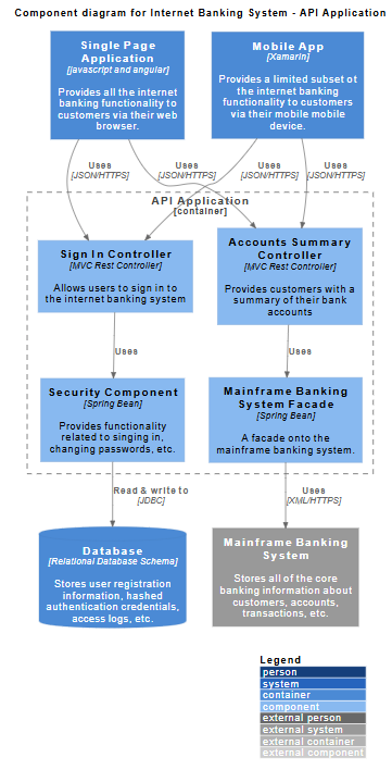
Purpose: To show how the "API Application" container is structured internally.
Key Findings:
The API Application is decomposed into logical software components:
- Controllers (Entry Points):
- Sign In Controller: Handles authentication requests.
- Accounts Summary Controller: Handles requests for account data.
- Tech: Both are MVC Rest Controllers.
- Business Logic/Services:
- Security Component: A Spring Bean responsible for signing in and password management. It reads/writes directly to the local Database via JDBC.
- Mainframe Banking System Facade: A Spring Bean that acts as an adapter. It translates API requests into calls the Mainframe understands (XML/HTTPS).
PlantUML Code:
@startuml
!include https://raw.githubusercontent.com/plantuml-stdlib/C4-PlantUML/master/C4_Component.puml

LAYOUT_WITH_LEGEND()

title Component diagram for Internet Banking System - API Application

Container(spa, "Single Page Application", "javascript and angular", "Provides all the internet banking functionality to customers via their web browser.")
Container(ma, "Mobile App", "Xamarin", "Provides a limited subset ot the internet banking functionality to customers via their mobile mobile device.")
ContainerDb(db, "Database", "Relational Database Schema", "Stores user registration information, hashed authentication credentials, access logs, etc.")
System_Ext(mbs, "Mainframe Banking System", "Stores all of the core banking information about customers, accounts, transactions, etc.")

Container_Boundary(api, "API Application") {
    Component(sign, "Sign In Controller", "MVC Rest Controller", "Allows users to sign in to the internet banking system")
    Component(accounts, "Accounts Summary Controller", "MVC Rest Controller", "Provides customers with a summary of their bank accounts")
    Component(security, "Security Component", "Spring Bean", "Provides functionality related to singing in, changing passwords, etc.")
    Component(mbsfacade, "Mainframe Banking System Facade", "Spring Bean", "A facade onto the mainframe banking system.")

    Rel(sign, security, "Uses")
    Rel(accounts, mbsfacade, "Uses")
    Rel(security, db, "Read & write to", "JDBC")
    Rel(mbsfacade, mbs, "Uses", "XML/HTTPS")
}

Rel(spa, sign, "Uses", "JSON/HTTPS")
Rel(spa, accounts, "Uses", "JSON/HTTPS")
Rel(ma, sign, "Uses", "JSON/HTTPS")
Rel(ma, accounts, "Uses", "JSON/HTTPS")

@enduml
Data Flow Example:
When a user requests an account summary via the Mobile App:
- Request hits Accounts Summary Controller.
- Controller uses Mainframe Banking System Facade.
- Facade calls the external Mainframe Banking System.
- Data is returned to the user.
6. Understanding C4 Supplementary Diagrams: The Landscape Diagram
Role and Purpose in the Modeling Process
The System Landscape Diagram is a supplementary diagram in the C4 Model that serves a unique and critical purpose in enterprise architecture documentation. While not one of the core four C4 levels (Context, Container, Component, Code), it provides essential context that other diagrams cannot.
Key Distinctions:
| Diagram Type |
Scope |
Focus |
Question It Answers |
| Landscape |
Enterprise-wide |
Multiple systems and actors |
"How does everything fit together across the entire organization?" |
| Context |
Single system |
One system and its immediate dependencies |
"What is this specific system and who uses it?" |
| Container |
Single system |
Technical architecture of one system |
"How is this system built and deployed?" |
| Component |
Single container |
Internal structure of a container |
"What are the internal components and how do they interact?" |
When to Use a Landscape Diagram
- Enterprise Architecture Planning: When you need to understand the complete ecosystem of systems, people, and interactions across an organization.
- Digital Transformation Initiatives: To map current state vs. future state across multiple systems and identify integration points.
- Stakeholder Communication: For C-level executives and business leaders who need to understand the big picture without getting lost in technical details.
- System Portfolio Management: To identify redundant systems, gaps in coverage, or opportunities for consolidation.
- Onboarding and Training: To help new employees understand how different parts of the organization interact and which systems support which business processes.
Key Concepts
1. Enterprise Boundary
The landscape diagram defines the scope of the enterprise or organizational unit being modeled. Everything inside the boundary is part of the organization; everything outside is external.
Example: In our case, "Big Bank plc" is the enterprise boundary containing all internal systems and staff.
2. Multiple Perspectives
Unlike the Context diagram which shows one system from one perspective, the Landscape diagram shows:
- Multiple systems working together
- Multiple user types (internal staff and external customers)
- Multiple interaction channels
- Cross-system workflows
3. System Relationships
Landscape diagrams reveal:
- Shared dependencies (e.g., Mainframe is used by ATM, Internet Banking, Customer Service, and Back Office)
- Integration patterns (e.g., Email system supports both customer and system communications)
- Service consumers and providers across the enterprise
4. Actor Classification
The diagram distinguishes between:
- Internal actors (employees, staff)
- External actors (customers, partners)
- System actors (automated systems, services)
Guidelines for Creating Effective Landscape Diagrams
DO:
- ✅ Start with the enterprise boundary - Clearly define what's inside and outside your organization.
- ✅ Group related elements - Use boundaries to show organizational units, departments, or business domains.
- ✅ Show all major systems - Include all significant systems that support the business processes you're modeling.
- ✅ Include both people and systems - Show how humans interact with systems and how systems interact with each other.
- ✅ Keep it high-level - Focus on systems, not containers or components. Save technical details for lower-level diagrams.
- ✅ Use consistent naming - System names should match across all C4 diagrams.
- ✅ Show key relationships - Focus on the most important interactions; you don't need to show every single relationship.
DON'T:
- ❌ Overcrowd the diagram - If you have more than 15-20 elements, consider creating multiple landscape diagrams for different business domains.
- ❌ Mix abstraction levels - Don't include containers or components; stick to systems only.
- ❌ Show technical protocols - Save protocol details (HTTPS, JDBC, etc.) for Container and Component diagrams.
- ❌ Forget external systems - Always show systems outside your enterprise that you depend on.
- ❌ Ignore non-human actors - Include automated systems, batch jobs, and external services.
Tips and Tricks
1. Use Color Coding Strategically
Blue = External people (customers, partners)
Green = Internal people (staff, employees)
Grey = Internal systems
Light Grey = External systems
This visual distinction helps viewers quickly understand the nature of each element.
2. Create Multiple Landscape Views
For large enterprises, create:
- Current State Landscape - Shows existing systems
- Future State Landscape - Shows target architecture
- Domain-Specific Landscapes - Focus on specific business areas (e.g., "Customer Service Landscape," "Operations Landscape")
3. Layer Information
Use tools that support layering to:
- Show/hide certain system categories
- Highlight specific workflows
- Create filtered views for different audiences
4. Document System Ownership
Add metadata to each system element:
- System owner/team
- Technology stack (brief)
- Criticality level
- Last updated date
5. Link to Other Diagrams
Reference your landscape diagram from:
- System Context diagrams (show which system you're zooming into)
- Architecture decision records (showing impact across the landscape)
- Project documentation (showing where new systems fit)
6. Maintain a System Registry
Use the landscape diagram as a visual index to a system catalog containing:
- System descriptions
- Integration points
- Data flows
- SLAs and dependencies
Common Pitfalls to Avoid
- Scope Creep: Trying to show every single system in the enterprise. Focus on systems relevant to your initiative or domain.
- Outdated Diagrams: Landscape diagrams become stale quickly. Establish a review cadence (quarterly or with major changes).
- Too Much Detail: Resist the urge to add technical details. That's what Container and Component diagrams are for.
- Missing Context: Don't show systems without explaining their purpose. Every system box should have a clear description.
- Ignoring Relationships: Showing systems without their relationships defeats the purpose. The value is in understanding how things connect.
Integration with Other C4 Diagrams
The Landscape diagram serves as the entry point to your C4 documentation:
System Landscape (Enterprise View)
        ↓
System Context (Single System View)
        ↓
Container Diagram (Technical Architecture)
        ↓
Component Diagram (Internal Structure)
        ↓
Code (Implementation)
Best Practice: Reference the Landscape diagram in your System Context diagram with a note like: "This system is part of the Big Bank plc enterprise landscape shown in Diagram L-001."
7. Key Concepts, Guidelines, and Tips & Tricks (Summary)
Based on this comprehensive case study, here are the core principles of the C4 model applied in practice:
A. Abstraction is Key (The "Zoom" Concept)
- Concept: Do not try to put everything on one diagram.
- Guideline: Start with the Landscape for enterprise context, then Context for system view. Only drill down to Container if you need to discuss deployment or technology stacks. Only drill down to Component if you are discussing code structure or specific logic flows.
- Tip: If a diagram has more than 10-12 boxes, it is likely too complex. Break it down.
B. Define Boundaries Clearly
- Concept: Distinguish between what you are building and what exists already.
- Guideline: Use dashed lines to group containers that belong to the same system (as seen in the Container Diagram with the "Internet Banking [system]" boundary). Use enterprise boundaries in Landscape diagrams.
- Tip: Always clearly label external systems (like the Mainframe) in grey or a different color to distinguish them from your own software.
C. Technology Choices Matter
- Concept: The C4 model encourages documenting technology decisions early.
- Guideline: Include technology tags in square brackets, e.g.,
[Java, Spring MVC] or [SQL Database].
- Tip: This helps the Operations team understand what needs to be supported (e.g., they need to support Docker containers and Java runtime environments).
D. Describe Relationships, Not Just Boxes
- Concept: A box is useless without knowing how it interacts with others.
- Guideline: Label the arrows. Don't just draw a line; say how they talk.
- Bad: Arrow from App to DB.
- Good: Arrow labeled "Reads from and writes to [sync, JDBC]".
- Tip: Specify the protocol (HTTPS, SMTP, JDBC) and the data format (JSON, XML) on the relationship lines. Exception: Landscape diagrams typically omit protocol details to maintain clarity.
E. Consistent Naming
- Concept: Avoid confusion between levels.
- Guideline: If a container is called "API Application" in Level 2, do not call it "Backend Service" in Level 3. Keep the names consistent.
- Tip: In the Component diagram, the "API Application" is shown as a container boundary (dashed box) to reinforce that the components inside belong to that specific container.
F. Choose the Right Diagram for the Audience
- Concept: Different stakeholders need different levels of detail.
- Guideline:
- C-Suite/Business Leaders: Landscape and Context diagrams
- Product Managers: Context and high-level Container diagrams
- Architects: All levels, especially Container
- Developers: Container and Component diagrams
- DevOps/Operations: Container diagrams with deployment details
- Tip: Create a "diagram index" that guides users to the right diagram for their needs.
G. Maintain Diagram Consistency
- Concept: Diagrams should tell a coherent story across levels.
- Guideline: Ensure element names, colors, and styles are consistent across all diagrams. Use a shared style guide.
- Tip: Use PlantUML or similar tools with shared includes to enforce consistency automatically.
H. Document Decisions, Not Just Structure
- Concept: Architecture diagrams should capture reasoning, not just boxes and lines.
- Guideline: Accompany diagrams with Architecture Decision Records (ADRs) explaining why certain choices were made.
- Tip: Link diagrams to ADRs (e.g., "See ADR-042 for rationale on choosing Angular for SPA").
8. Conclusion
This case study demonstrates how the C4 Model, supplemented with Landscape diagrams, provides a comprehensive framework for documenting software architecture at multiple levels of abstraction. By starting with an enterprise-wide view and progressively zooming in to component-level details, we can:
- Communicate effectively with stakeholders at all levels
- Make informed decisions about technology and architecture
- Onboard new team members quickly with clear documentation
- Maintain alignment between business goals and technical implementation
- Manage complexity by separating concerns across different diagram types
The addition of the System Landscape diagram provides crucial context that helps stakeholders understand where the Internet Banking System fits within the broader ecosystem of Big Bank plc, making it an invaluable tool for enterprise architecture planning and communication.
By following the guidelines, concepts, and tips outlined in this case study, teams can create clear, maintainable, and useful architecture documentation that serves both current and future needs.