
Software architecture documentation is often a bottleneck—time-consuming, error-prone, and quickly outdated. The C4 model provides a structured hierarchy for visualizing architecture, while modern tools like Visual Paradigm's AI-powered C4 PlantUML Studio and OpenDocs platform transform how teams create, maintain, and share architectural documentation.
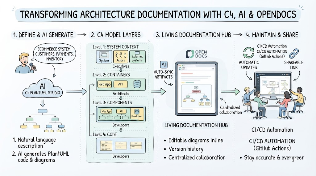
This guide covers the complete workflow: understanding the C4 model, generating diagrams with AI assistance, using PlantUML code, embedding artifacts in OpenDocs, and establishing a living documentation practice.
The C4 model, created by Simon Brown, provides four levels of abstraction that allow different stakeholders to view the system at the appropriate level of detail .
| Level | Purpose | Audience | Example |
|---|---|---|---|
| Level 1: Context | System in its environment, showing users and external systems | Executives, non-technical stakeholders | E-commerce platform interacting with users, payment gateways, inventory |
| Level 2: Containers | Deployable units (apps, databases, microservices) | DevOps, architects | Frontend (React), Backend (Node.js), Database (PostgreSQL) |
| Level 3: Components | Internal modules and their interactions | Developers, technical leads | User Service, Order Service, Payment Processor |
| Level 4: Code | Class-level details (optional) | Developers implementing features | UserRepository, OrderController |
The power of C4 lies in treating diagrams like code—version-controlled, collaborative, and automatable .
Visual Paradigm's AI-driven C4 PlantUML Studio provides a guided workflow that transforms natural language descriptions into complete, multi-level C4 models.
Core Capabilities:
OpenDocs serves as the bridge between diagrams and documentation, functioning like a supercharged Notion with professional diagramming built in.
Key Features:
Start with a clear system description—this guides all subsequent AI generation. The AI can help generate a comprehensive problem statement from a simple project name.
Example for a Warehouse Management System :
Project: Warehouse Management System
Description: System for warehouse staff, managers, and logistics teams
to manage inventory, optimize storage, and coordinate with ERP and
Order Management systems.
Best Practice: The quality of AI-generated diagrams directly correlates with the clarity of your problem statement.
The AI reads your problem statement and generates a Context diagram showing the system as a single entity with external actors and systems.
PlantUML VPasCode (by Visual Paradigm) Example – Context Diagram :
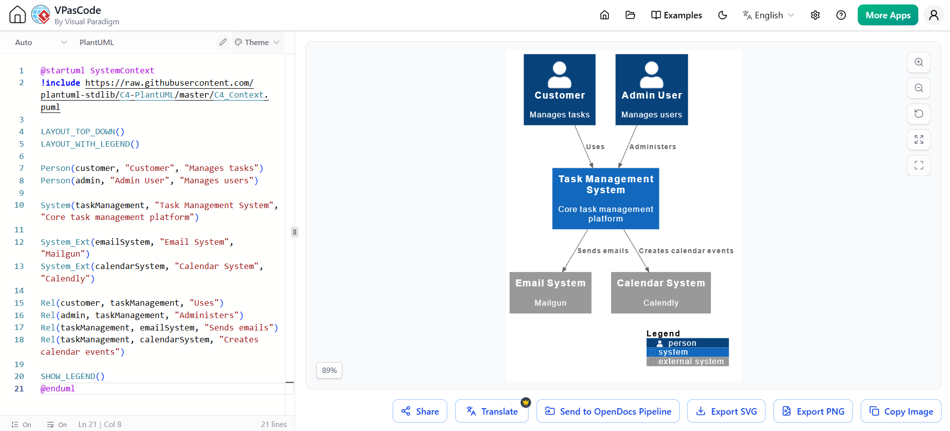
@startuml SystemContext
!include https://raw.githubusercontent.com/plantuml-stdlib/C4-PlantUML/master/C4_Context.puml

LAYOUT_TOP_DOWN()
LAYOUT_WITH_LEGEND()

Person(customer, "Customer", "Manages tasks")
Person(admin, "Admin User", "Manages users")

System(taskManagement, "Task Management System", "Core task management platform")

System_Ext(emailSystem, "Email System", "Mailgun")
System_Ext(calendarSystem, "Calendar System", "Calendly")

Rel(customer, taskManagement, "Uses")
Rel(admin, taskManagement, "Administers")
Rel(taskManagement, emailSystem, "Sends emails")
Rel(taskManagement, calendarSystem, "Creates calendar events")

SHOW_LEGEND()
@enduml
The AI leverages the context diagram to generate a more detailed view showing deployable units, technologies, and communication paths.
PlantUML VPasCode Example – Container Diagram :
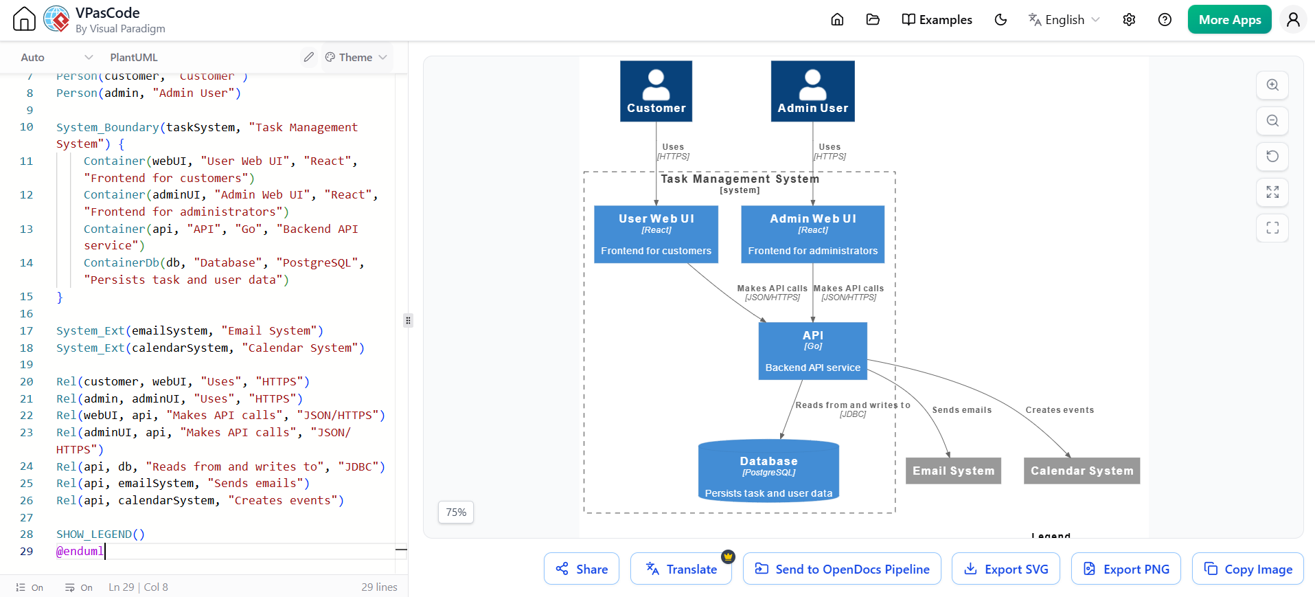
@startuml ContainerDiagram
!include https://raw.githubusercontent.com/plantuml-stdlib/C4-PlantUML/master/C4_Container.puml

LAYOUT_TOP_DOWN()
LAYOUT_WITH_LEGEND()

Person(customer, "Customer")
Person(admin, "Admin User")

System_Boundary(taskSystem, "Task Management System") {
    Container(webUI, "User Web UI", "React", "Frontend for customers")
    Container(adminUI, "Admin Web UI", "React", "Frontend for administrators")
    Container(api, "API", "Go", "Backend API service")
    ContainerDb(db, "Database", "PostgreSQL", "Persists task and user data")
}

System_Ext(emailSystem, "Email System")
System_Ext(calendarSystem, "Calendar System")

Rel(customer, webUI, "Uses", "HTTPS")
Rel(admin, adminUI, "Uses", "HTTPS")
Rel(webUI, api, "Makes API calls", "JSON/HTTPS")
Rel(adminUI, api, "Makes API calls", "JSON/HTTPS")
Rel(api, db, "Reads from and writes to", "JDBC")
Rel(api, emailSystem, "Sends emails")
Rel(api, calendarSystem, "Creates events")

SHOW_LEGEND()
@enduml
The AI drills into a specific container to show internal components, their responsibilities, and interactions.
PlantUML VPasCode Example – Component Diagram:
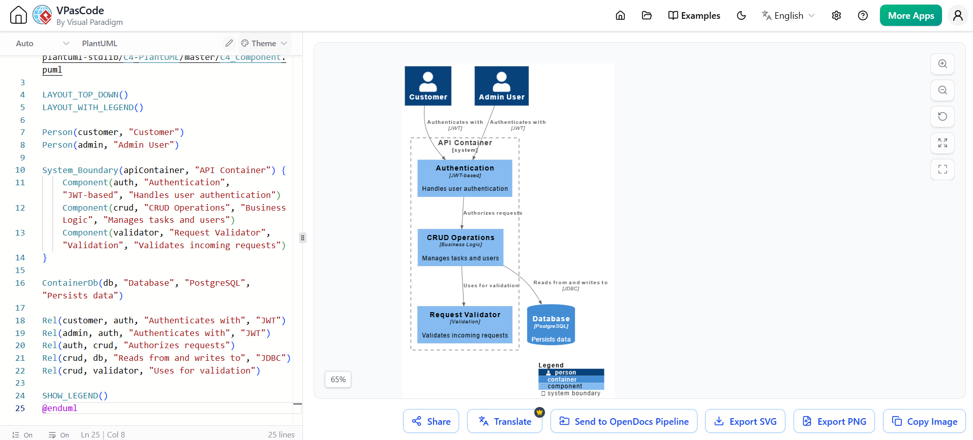
@startuml ComponentDiagram
!include https://raw.githubusercontent.com/plantuml-stdlib/C4-PlantUML/master/C4_Component.puml

LAYOUT_TOP_DOWN()
LAYOUT_WITH_LEGEND()

Person(customer, "Customer")
Person(admin, "Admin User")

System_Boundary(apiContainer, "API Container") {
    Component(auth, "Authentication", "JWT-based", "Handles user authentication")
    Component(crud, "CRUD Operations", "Business Logic", "Manages tasks and users")
    Component(validator, "Request Validator", "Validation", "Validates incoming requests")
}

ContainerDb(db, "Database", "PostgreSQL", "Persists data")

Rel(customer, auth, "Authenticates with", "JWT")
Rel(admin, auth, "Authenticates with", "JWT")
Rel(auth, crud, "Authorizes requests")
Rel(crud, db, "Reads from and writes to", "JDBC")
Rel(crud, validator, "Uses for validation")

SHOW_LEGEND()
@enduml
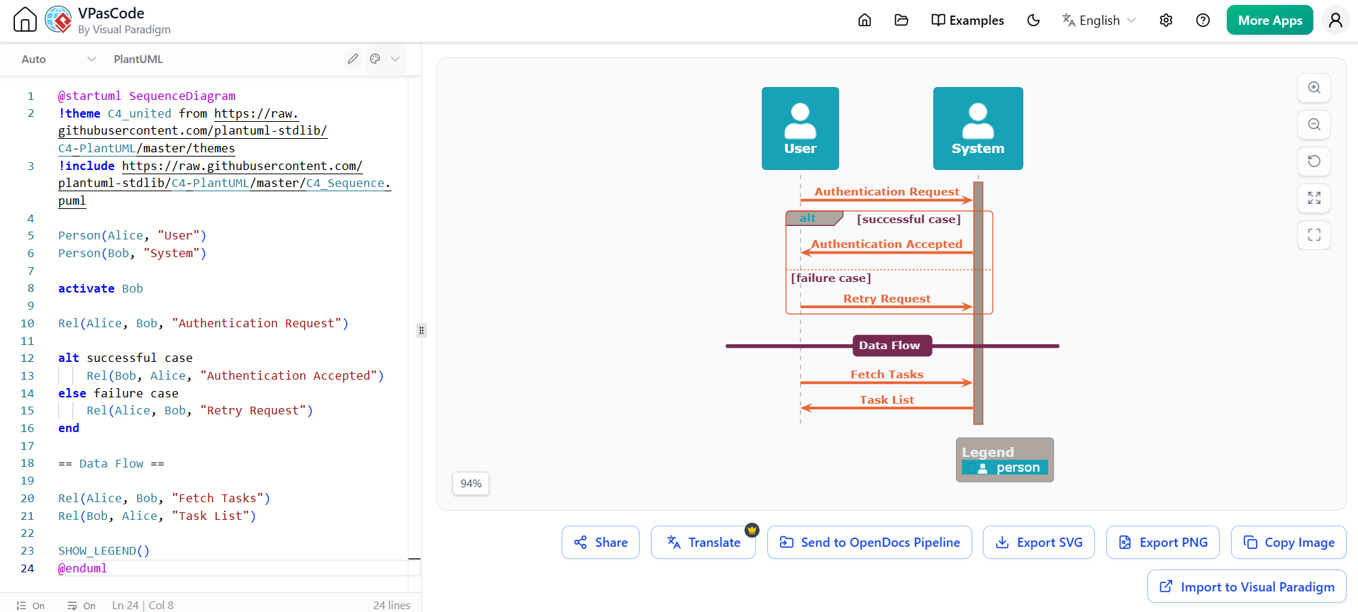
Beyond the core four levels, generate Sequence, Deployment, and Landscape diagrams for specific audiences.
Sequence Diagram Example (C4_Sequence.puml):
@startuml SequenceDiagram
!theme C4_united from https://raw.githubusercontent.com/plantuml-stdlib/C4-PlantUML/master/themes
!include https://raw.githubusercontent.com/plantuml-stdlib/C4-PlantUML/master/C4_Sequence.puml

Person(Alice, "User")
Person(Bob, "System")

activate Bob

Rel(Alice, Bob, "Authentication Request")

alt successful case
    Rel(Bob, Alice, "Authentication Accepted")
else failure case
    Rel(Alice, Bob, "Retry Request")
end

== Data Flow ==

Rel(Alice, Bob, "Fetch Tasks")
Rel(Bob, Alice, "Task List")

SHOW_LEGEND()
@enduml
C4-PlantUML provides layout macros for controlling diagram orientation:
!include https://raw.githubusercontent.com/plantuml-stdlib/C4-PlantUML/master/C4_Container.puml

' Default – top to bottom
LAYOUT_TOP_DOWN()

' Left to right layout
LAYOUT_LEFT_RIGHT()

' Landscape mode (left to right with directed relations)
LAYOUT_LANDSCAPE()

' Add legend
LAYOUT_WITH_LEGEND()

' Sketch mode (indicates diagram is a draft)
LAYOUT_AS_SKETCH()
Customize person representations :
Person(userA, "User A", "Default sprite", "person")
Person(userB, "User B", "Custom sprite", "person2")

' Hide sprites entirely
HIDE_PERSON_SPRITE()

' Show with custom sprite
SHOW_PERSON_SPRITE(spriteName)
C4_Context.pumlC4_Container.pumlC4_Component.pumlC4_Sequence.pumlSHOW_LEGEND() last in the diagram fileRel(from, to, "Description", "Technology")Recent research on LLMs for C4 diagram generation reveals important insights :
Strengths:
Limitations:
LLM Performance Comparison:
Bad Prompt:
"Generate C4 diagrams for my banking app"
Good Prompt:
"You are a software architect. Create C4 diagrams for the Panda Service – an ML-based product recommendation service for a bank. The system must:
- Leverage user account behavior and transaction history
- Generate personalized product recommendations
- Be accessible via internal banking apps, web, and mobile
- Consider banking regulations and security
Generate:
- Level 1: System Context Diagram
- Level 2: Container Diagram showing deployable services
- Level 3: Component Diagram for the Model Inference Service"
Emerging approaches use collaborative LLM agents that simulate role-specific experts (architect, developer, security expert) to analyze requirements and generate C4 views simultaneously . This improves structural integrity and consistency across diagram levels.
| Feature | Description |
|---|---|
| Inline Diagramming | Create, edit, and view diagrams inside documentation |
| AI Generation | Type description → AI generates diagram instantly |
| Version History | Track changes to both text and diagrams |
| Export | PNG, SVG, PDF, PlantUML, interactive HTML |
| Team Collaboration | Share editable links, branch, merge |
OpenDocs provides AI-powered generation for C4 diagrams, including System Context, Container, Component, and Deployment diagrams .
The combination of the C4 model, AI-assisted generation, and living documentation platforms transforms software architecture practice from a tedious, manual chore into a streamlined, collaborative workflow.
Key Takeaways:
By adopting these practices, teams maintain clear, accurate, and evolving architectural documentation without the traditional maintenance burden.
Looking for a powerful, free diagram-as-code tool? Effortlessly render PlantUML, Mermaid, Graphviz, and 20+ programming languages in real time—powered by instant AI error fixing and automatic format detection.

