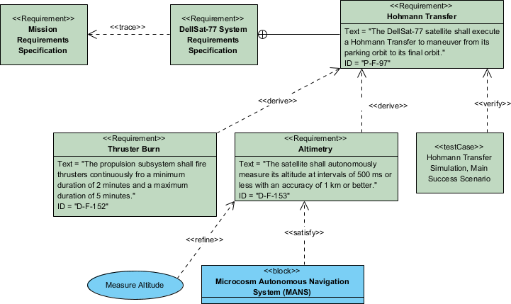
A requirements diagram is the primary modeling for communicating system requirements in MBSE that are specified in the text. Modelers commonly create requirements diagrams to convey traceability among requirements and traceability from requirements to system structures and behaviors.
The requirements diagram is used to display text-based requirements, the relationships between requirements (containment, derive requirement, and copy), and the relationships between requirements and the other model elements that satisfy, verify and refine them. It is useful for requirements engineering, including requirements verification and validation (V&V).
Example: Hohmann Transfer Requirement Traceability
(* Source: Example adopted from – SysML Distilled by Lenny Delligatti, P.203)

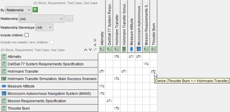
Matrices are a staple in systems engineering documentation. A matrix is not a graphical notation (as most SysML notations are). However, SysML supports matrix notation because it is simply the best mechanism for expressing many relationships in the least amount of space.
The matrix shown in Matrix below expresses all of the dependency-based requirements relationships that are displayed in the Requirement Diagram Example above.

Tables, like matrices, are commonplace in systems engineering documentation. And like matrices, SysML supports tables because they are a space-efficient mechanism for expressing a lot of information.
For Example, We can use Visual Paradigm’s ETL Table feature to represent text-based requirements and their relationship with other requirements, design elements, and test cases to support requirements traceability as shown in the table below:
