Model-based systems engineering (MBSE) is a systems engineering methodology that focuses on creating and exploiting domain models as the primary means of information exchange between engineers, rather than on document-based information exchange.
Model-Based Systems Engineering (MBSE) is the practice of developing a set of related system models that help define, design, and document a system under development. These models provide an efficient way to explore, update, and communicate system aspects to stakeholders, while significantly reducing or eliminating dependence on traditional documents. In practice, engineers use models to gain knowledge (e.g. performance) and to serve as a guide for system implementation (e.g. SysML, UML).
A recommended best practice for any Model-Based Systems Engineering (MBSE) approach is the synergistic application of Model-Based Languages, Model-Based Tools, Model-Based Processes, and Model-Based Architecture Frameworks, as shown in the System Architecture Tetrad figure below. After a decade of pragmatic experience applying SysML to tough Systems Engineering problems, SysML has emerged as the de facto Model-Based Language choice for MBSE projects.
| Learn SysML Faster, Better and Easier |
| Are you looking for a Free SysML tool for learning SysML faster, easier and quicker? Visual Paradigm Community Edition is a SysML software that supports all SysML diagram types. It is an international award-winning SysML modeler, and yet it is easy-to-use, intuitive & completely free. |
| [Free Download] |
The term Model-Based Systems Engineering and its acronym MBSE are popular among Systems Engineers who advocate the use of SysML as a standard architecture modeling language for Systems Engineering applications, and who want to distinguish their approach from Model-Driven Development and its variants, which tend to be software centric.
SysML (Systems Modeling Language) is based on UML and replaces the modeling of classes and objects by block modeling for a vocabulary more suited to System Engineering. A block encompasses all software, hardware, data, process, and even people management concepts.
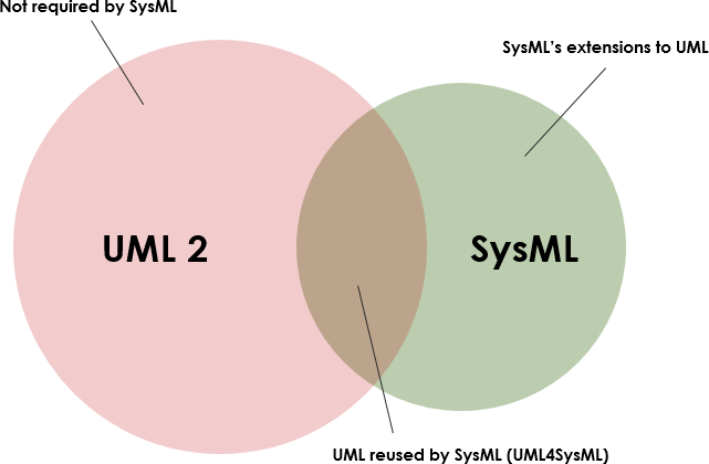
SysML reuses part of UML2 and it also provides its own definitions (SysML extensions) as shown in the Figure below:

UML4SysML:
SysML Extensions:
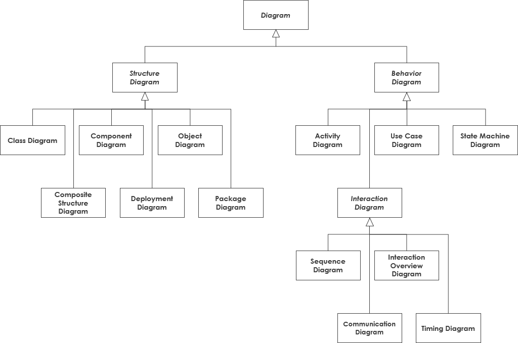
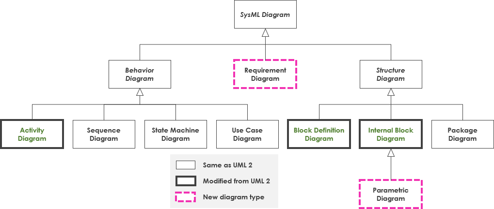
The diagrams defined under UML2, and those that make up SysML are shown below. Apart from the new features, the majority of the changes made by SysML can be found in the structural diagrams.
UML2: 13 diagrams – 6 structural, and 7 dynamic

SysML: 9 diagrams – 4 structural, 4 dynamic, and the requirements diagram:

The advantages of SysML over UML for systems engineering become obvious when considering a concrete example, like modeling an automotive system. With SysML one can use Requirement diagrams to efficiently capture functional, performance, and interface requirements, whereas with UML one is subject to the limitations of use case diagrams to define high-level functional requirements. Likewise, with SysML one can use Parametric diagrams to precisely define performance and quantitative constraints like maximum acceleration, minimum curb weight, and total air conditioning capacity. UML provides no straightforward mechanism to capture this sort of essential performance and quantitative information.
SysML offers systems engineers several noteworthy improvements over UML, which tends to be software-centric. These improvements include the following:
Consequent to these enhancements, SysML is able to model a wide range of systems, which may include hardware, software, information, processes, personnel, and facilities.
| Try to Draw SysML Diagram Now |
| You’ve learned what SysML is and how to draw SysML diagram. It’s time to draw a SysML Diagram of your own. Get Visual Paradigm Community Edition, a free SysML software, and create your own SysML diagram with the free SysML diagram tool. It’s easy-to-use and intuitive. |
| [Free Download] |