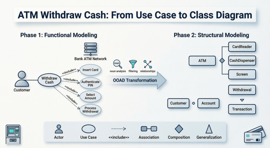
This case study documents the systematic transition from a UML Use Case Diagram to a UML Class Diagram within the context of an Automated Teller Machine (ATM) system. Focusing exclusively on the "Withdraw Cash" functionality, the study demonstrates how Object-Oriented Analysis and Design (OOAD) bridges the gap between what a system does (functional requirements) and how it is structured to achieve it (static architecture). The analysis outlines the methodological transformation steps, applies core UML concepts, and establishes actionable design guidelines for producing robust, maintainable software blueprints.
ATM systems require high reliability, strict security, and clear separation between user interactions, business logic, and hardware control. The "Withdraw Cash" operation is a high-frequency, mission-critical workflow that serves as an ideal modeling candidate.
Primary Objectives:
Translate user-centric functional requirements into a precise object-oriented architecture.
Demonstrate a repeatable, step-by-step methodology for converting Use Case Diagrams to Class Diagrams.
Apply and differentiate core UML relationships (Association, Composition, Generalization, <<include>>).
Establish traceability between stakeholder requirements and technical implementation.
The foundation of the design process begins with capturing system behavior from the user's perspective.
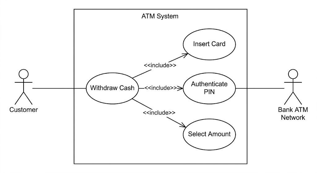
Primary Actor: Customer (The entity initiating and driving the transaction).
Secondary/External Actor: Bank ATM Network (The external system responsible for authorization, fund verification, and account updates).
The primary goal, "Withdraw Cash", is decomposed into mandatory, sequential sub-processes. In UML, this is modeled using the <<include>> relationship, indicating that the base use case cannot proceed without these components:
Insert Card
Authenticate PIN
Select Amount
Process Withdrawal
Design Insight: The <<include>> relationship explicitly enforces workflow dependencies, ensuring that authentication and card validation are non-negotiable prerequisites for fund dispensing.
The transition to the Class Diagram requires shifting focus from behavioral flows to static structure, state, and object interactions.
Scanning the use case specifications yields initial candidate entities:
Customer, Card, PIN, Account, ATM, CashDispenser, Screen, Transaction, Withdrawal.
Not all nouns warrant independent classes. Entities are evaluated based on whether they encapsulate meaningful state (attributes) and behavior (methods):
PIN is refined to an authentication parameter, not a standalone class.
Withdrawal is recognized as a specialized type of Transaction, enabling logical hierarchy.
Hardware/UI elements (CardReader, CashDispenser, Screen) are encapsulated as subsystems within the ATM.
| Class | Key Attributes | Key Operations |
|---|---|---|
Card |
cardNumber, expiryDate, status |
validate(), readChip() |
Account |
accountNumber, balance, status |
verifyBalance(), debit(amount), getHistory() |
ATM |
atmID, location, cashLevel |
insertCard(), authenticatePIN(), requestWithdrawal(), dispenseCash() |
Transaction |
transactionID, timestamp, status, amount |
initiate(), complete(), log() |
Withdrawal |
(Inherits all from Transaction) | verifyLimits(), authorizeNetwork() |
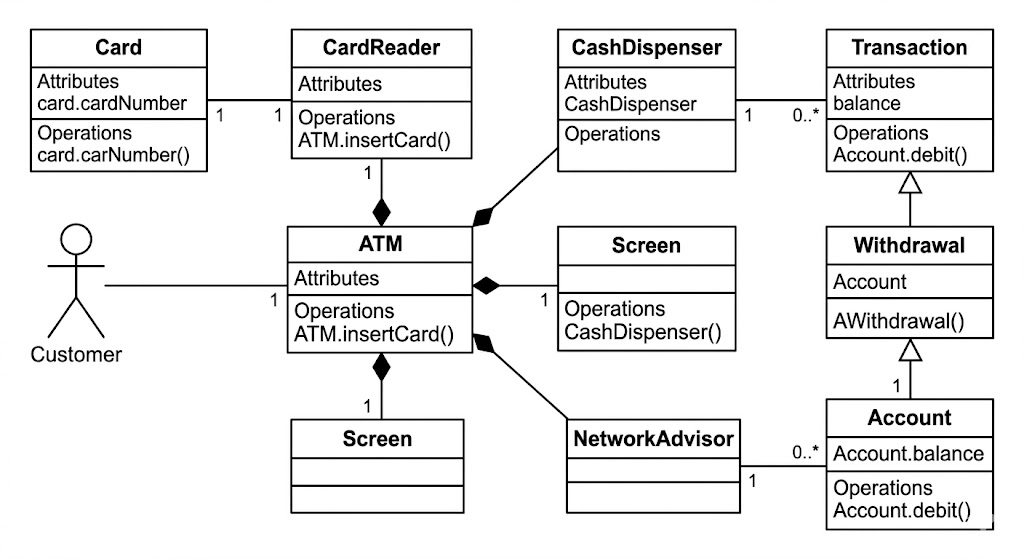
Association (───): A Customer maintains an Account. A Transaction records a link to an Account to reflect financial impact.
Composition (Filled Diamond ◆───): The ATM owns its sub-components (CardReader, CashDispenser, Screen). This strong lifecycle dependency means these components cannot exist independently of the ATM in this domain model.
Generalization/Inheritance (Hollow Triangle △───): Withdrawal is a type of Transaction. This enables polymorphism and promotes code reuse for common transaction behaviors (e.g., logging, timestamping, status tracking).
| Concept | Definition in Context |
|---|---|
| Actor | External entity interacting with the system boundary (Customer, Bank Network). |
| Use Case | A complete sequence of actions to achieve a goal (Withdraw Cash). |
<<include>> |
Mandatory inclusion relationship showing that sub-use cases are required by the base use case. |
| Class | Blueprint defining shared attributes and operations for system objects. |
| Association | Semantic relationship indicating objects know of and interact with each other. |
| Composition | Strong "whole-part" relationship where parts cannot exist without the whole. |
| Generalization | Inheritance relationship (is-a-type-of) enabling hierarchical modeling. |
| Multiplicity | Defines cardinality of relationships (e.g., 1 ATM to 1..* Transactions). |
Maintain Traceability: Every major use case must map to at least one class, attribute, or operation. Unmapped classes indicate scope creep; unmapped use cases indicate missing architecture.
Use Correct Line Styles:
Solid lines for Associations/Compositions
Solid lines with hollow triangles for Generalization
Dashed lines with <<include>>/<<extend>> stereotypes for Use Case relationships
Apply Multiplicity Rigorously: Specify bounds (e.g., 0..*, 1, 1..*) to clarify whether relationships are optional, mandatory, singular, or plural.
Avoid Noun-Verb Traps: Do not create a class for every noun. Filter by domain relevance, state, and behavior.
Encapsulate Hardware Complexity: Hide low-level hardware interactions behind high-level controller interfaces (e.g., ATM manages CashDispenser internally; the Customer only interacts with ATM).
| Challenge | Mitigation |
|---|---|
Over-Engineering Classes (e.g., modeling Screen or PIN as independent domain objects) |
Apply the Domain Relevance Filter: If an entity only exists to support a UI or parameterize a method, model it as an attribute or component, not a standalone class. |
Confusing <<include>> vs <<extend>> |
Use <<include>> for mandatory steps (Card, PIN). Reserve <<extend>> for conditional/optional flows (e.g., Print Receipt, Check Balance). |
| Ambiguous Relationship Ownership | Apply the Lifecycle Test: If the ATM is decommissioned, do the hardware modules exist independently in this domain? If no, use Composition (◆), not Aggregation or Association. |
| Loss of Requirement Traceability | Maintain a traceability matrix linking each Use Case → Class → Method. Conduct peer reviews to ensure functional coverage matches structural design. |
The transformation of the ATM "Withdraw Cash" Use Case Diagram into a Class Diagram exemplifies the power of disciplined UML modeling. By systematically identifying actors, decomposing workflows, filtering entities into meaningful classes, and mapping precise relationships, development teams can create structural blueprints that are functionally accurate, technically sound, and highly maintainable.
This case study reinforces that UML is not merely a documentation tool, but a critical analytical framework. When applied correctly, it reduces architectural ambiguity, aligns stakeholder expectations with engineering implementation, and lays a scalable foundation for secure, real-world software systems.
Online Use Case Diagram Tool: Make professional Use Case Diagram in minutes with Visual Paradigm Online. Create use case diagrams easily with the drag and drop editor, design with the rich set of UML symbols, keep your design in a cloud workspace and work collaboratively with your team. Export and share your works via a collection of image and document formats like PNG, JPG, GIF, SVG and PDF.
Step-by-step Class Diagram Tutorial using Visual Paradigm: A comprehensive tutorial that walks you through the process of creating a class diagram using Visual Paradigm, detailing the steps from opening the tool to finalizing the diagram. Learn what a class diagram is, why and when to use it, and how to create classes, define attributes and methods, establish relationships, and define inheritance.
Use Case Diagram Tutorial - YouTube: Video tutorial on creating use case diagrams.
Class Diagram Tutorial - YouTube: Video tutorial on creating class diagrams.
Use case diagram - Visual Paradigm User Guide: Learn how to draw use case diagrams, understand use case diagram notations, and document use case details. This chapter covers how to model system functions (goals) as well as the actors that interact with those functions.
Documenting use case details: Learn how to document the details of use cases including basic information, flow of events, requirements and test plan. Documenting use case details is essential in recording meaningful and important information for a use case.
What is Use Case Diagram?: A comprehensive guide explaining what a use case diagram is, its purpose, and why use cases are important in software development. Learn about use case modeling techniques, actors, use cases, system boundaries, and relationships including extends, include, and generalization.
What is Use Case Diagram?: (Duplicate of #7) A comprehensive guide explaining what a use case diagram is, its purpose, and why use cases are important in software development.
Use Case Diagram Solution: Capture functional requirements by UML use case diagram, design use case scenarios with flow of event editor, and design acceptance testing procedure. Learn to capture user's requirements by focusing on who (actor) wants to do what (use case) with the system.
Use Case Diagram Tutorial - YouTube: Learn how to create a Use Case Diagram using both manual tools and AI-powered generation.
What is Use Case Diagram?: (Duplicate of #7) A comprehensive guide explaining what a use case diagram is and its role in system/software requirements.
UML Class Diagram Tutorial: The UML Class diagram is a graphical notation used to construct and visualize object oriented systems. Learn about classes, attributes, operations, relationships including inheritance, association, aggregation, composition, dependency, and realization with practical examples.
Step-by-step Class Diagram Tutorial using Visual Paradigm: (Duplicate of #2) A comprehensive tutorial on creating class diagrams using Visual Paradigm.
blog.visual-paradigm.com/step-by-step-class-diagram-tutorial-using-visual-paradigmClass Diagram Tutorial - YouTube: Video tutorial on class diagrams.
Synchronizing Object Model and Data Model: Learn how to synchronize object model and data model in Visual Paradigm.
Class Diagram Presentation Options: Learn about different presentation options for class diagrams.