In today's rapidly evolving software development landscape, creating robust, scalable, and maintainable applications requires more than just writing code—it demands thoughtful design and clear communication among stakeholders. Unified Modeling Language (UML) serves as a universal visual language that bridges the gap between conceptual requirements and technical implementation.
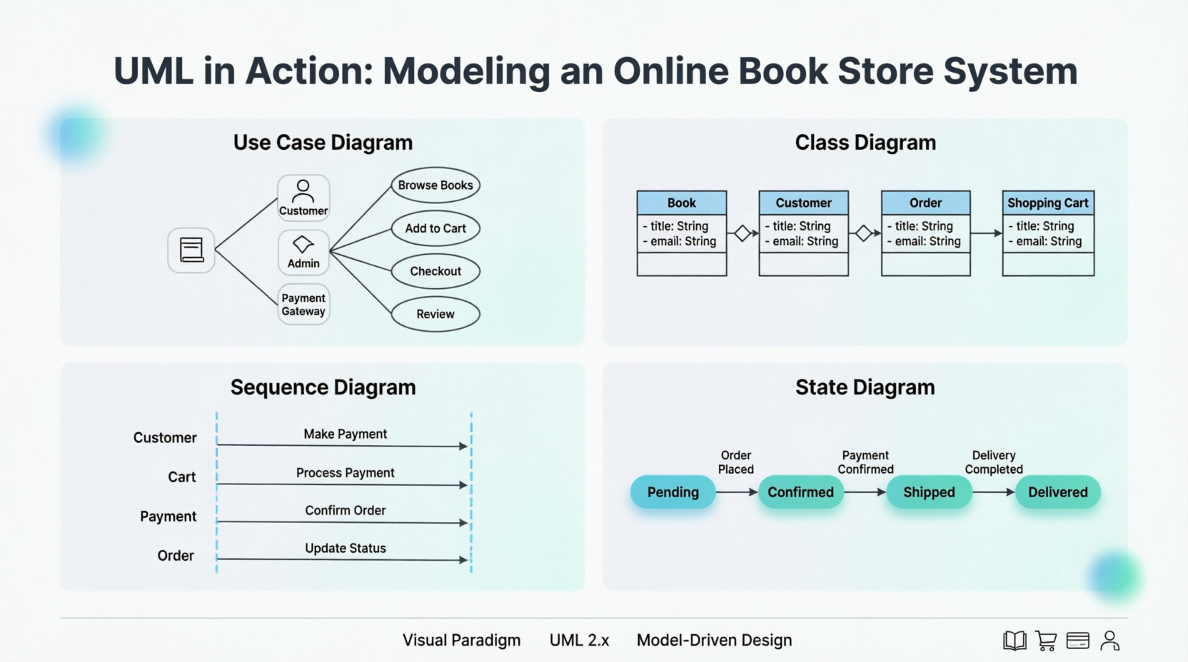
This comprehensive guide explores how UML diagrams—specifically Use Case, Class, Sequence, and State diagrams—can be effectively applied to model a real-world online book store application. Whether you're a seasoned software architect, a product manager coordinating cross-functional teams, or a student learning system design principles, this guide provides practical insights into leveraging UML to capture requirements, define system structure, model interactions, and manage object lifecycles. By the end of this article, you'll understand not only how to create these diagrams but also how they work together to form a cohesive, actionable blueprint for successful software delivery.
An online book store application is designed to allow customers to browse, search, purchase, and review books. The application must handle multiple customer interactions and interactions with various external systems like payment gateways and inventory systems.
The use case diagram is the first step in UML modeling. It describes the external actors that interact with the system and the functionalities the system provides.
The use case diagram helps identify:
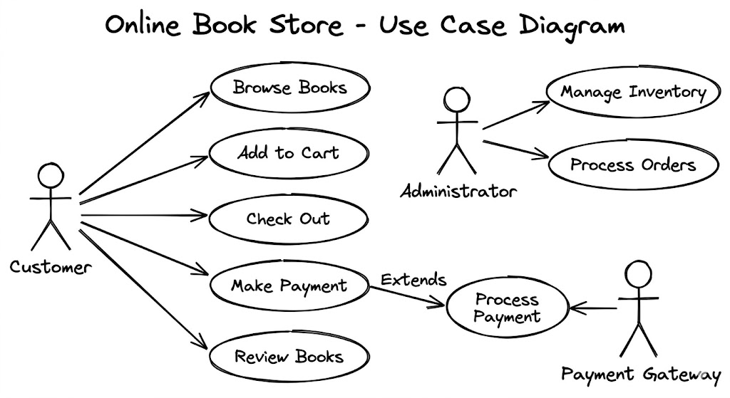
Actors:
Customer: Browses books, adds books to cart, checks out, makes payments, reviews books.
Administrator: Adds, updates, and deletes books from the inventory, manages customer accounts, processes orders.
Payment Gateway: Processes payment transactions.
Use Cases:
Browse Books: Customers can browse books by category, author, or title.
Add to Cart: Customers can add books to their shopping cart.
Check Out: Customers can proceed to checkout after adding books to the cart.
Make Payment: Customers can pay for their purchases using a secure payment gateway.
Review Books: Customers can rate and review books they have purchased.
Manage Inventory: Administrators can add, update, and delete books from the inventory.
Process Orders: Administrators can process customer orders.
The class diagram describes the static structure of the system, including the classes, their attributes, operations, and the relationships between them.
The class diagram helps to:
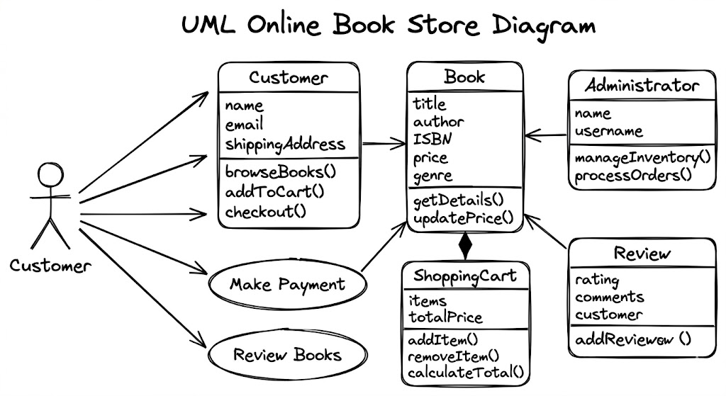
Identify Key Classes:
Book: Represents a book with attributes like title, author, ISBN, price, and genre.
Customer: Represents a customer with attributes like name, email, and shipping address.
Shopping Cart: Represents a customer's shopping cart with a collection of books and their quantities.
Order: Represents an order placed by a customer with details like customer information, ordered books, shipping address, and payment status.
Payment: Represents a payment transaction with details like amount, date, and payment status.
Review: Represents a customer's review for a book with rating and comments.
Administrator: Represents an administrator with attributes like name and username.
Define Relationships:
Association: For example, a customer has a shopping cart.
Aggregation: For example, an order contains a list of items.
Inheritance: For example, both Customer and Administrator inherit from a common User class.
Composition: For example, a shopping cart is composed of items.
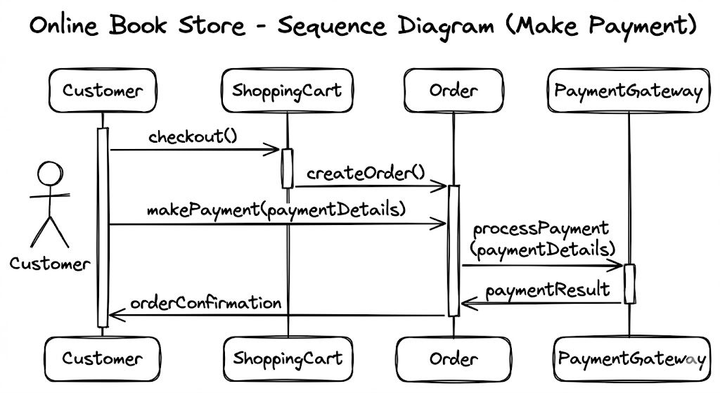
The sequence diagram shows the interaction between objects in a sequential manner. It shows the order in which messages are exchanged between objects to achieve a specific functionality.
The sequence diagram helps to:
Model User Interactions: It helps to understand the typical flow of interaction for a specific use case, such as 'Make Payment' in our example.
Visualize Object Communication: It helps to identify the sequence of method calls and messages exchanged between objects.
The state diagram describes the lifecycle of an object, showing the states an object can be in and the transitions between those states.
The state diagram helps to:
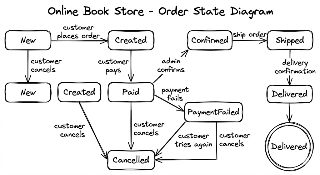
Define Object Behavior: It is useful for describing the behavior of objects that have a well-defined lifecycle, such as an order.
Identify Events and Transitions: It shows the events that cause transitions from one state to another and the actions associated with those transitions.
The various UML diagrams provide different perspectives on the system, and each diagram type offers unique insights into the system's design and behavior. By combining different UML diagrams, including the state diagram, a more complete and accurate model of the system can be developed.
Visual Paradigm provides comprehensive support for all 14 UML 2.x diagram types, including use case, class, sequence, and state diagrams. Its toolset is designed to bridge the gap between requirements and implementation through a combination of manual modeling, automated features, and AI-powered assistance.
Use Case Diagrams: Used to capture system requirements and goals from an external perspective. Visual Paradigm supports documenting full "stories" using the flow of events editor and use case details.
Class Diagrams: Represent the static structure of a system, including objects, attributes, and operations. Visual Paradigm supports real-time code synchronization, reverse engineering, and sharing model elements across multiple diagrams.
Sequence Diagrams: A type of interaction diagram that emphasizes the time-ordering of messages between objects. The resource catalog tool allows for rapid creation of lifelines and messages.
State Machine Diagrams: Used for modeling the dynamic behavior of objects by illustrating state transitions. The tool supports generating and reversing code directly from state machines.
AI Diagram Generator: Instantly generate any of these four diagram types from textual descriptions using an AI chatbot.
Multi-Platform Access: Modeling can be done via the Desktop client or Online tool, both supporting real-time team collaboration.
Code & Database Engineering: Beyond drawing, Visual Paradigm facilitates code generation for over 10 languages and database synchronization between ER diagrams and class diagrams.
Free for Learning: The Community Edition provides free access to all major UML diagram types for non-commercial use.
Modeling complex systems like an online book store requires more than intuition—it demands structure, clarity, and collaboration. UML diagrams provide the visual vocabulary to translate abstract requirements into concrete, actionable designs. Use Case diagrams align stakeholders on functionality; Class diagrams establish the system's architectural backbone; Sequence diagrams clarify dynamic interactions; and State diagrams manage complex object lifecycles.
When used together, these diagrams form a powerful toolkit that reduces ambiguity, accelerates development, and improves maintainability. Tools like Visual Paradigm further enhance this process by offering AI-assisted generation, real-time collaboration, and seamless integration with code and databases—making professional-grade modeling accessible to teams of all sizes.
Whether you're designing your first e-commerce platform or refining an enterprise-scale application, embracing UML modeling practices empowers you to build systems that are not only functional but also resilient, scalable, and aligned with business goals. Start modeling today, and transform your ideas into well-architected reality.