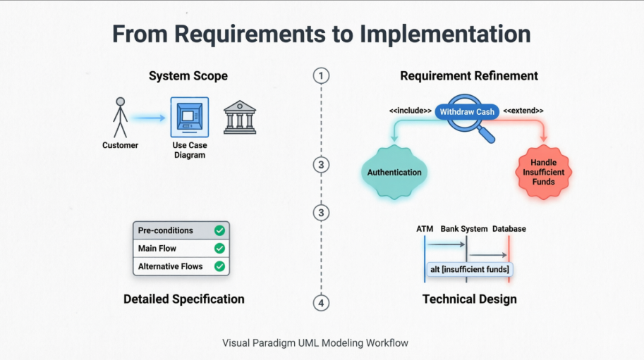
In modern software engineering, bridging the gap between business requirements and technical implementation is critical for building robust, user-centered systems. Use case modeling serves as a powerful technique to capture functional requirements, define system boundaries, and clarify interactions between actors and the system. This tutorial walks you through a complete, end-to-end analysis of an ATM "Withdraw Cash" use case—progressing from high-level conceptual diagrams to detailed behavioral specifications and technical sequence diagrams.
Using Visual Paradigm's comprehensive UML modeling suite, you'll learn how to:
Define system scope and actor relationships through use case diagrams
Document detailed flow logic with structured use case descriptions
Translate requirements into executable sequence diagrams
Leverage automation features to maintain traceability and accelerate design
Whether you're a business analyst, product owner, or software architect, this guide provides practical, actionable insights for modeling real-world transactional systems with clarity and precision.
We begin with the overall System Use Case Diagram. This diagram defines the boundaries of the ATM system, the external actors (Customer and Bank System), and the primary goals (Use Cases) the system must support. 'Withdraw Cash' is identified as a core function that interacts with both the Customer and the Bank's backend.
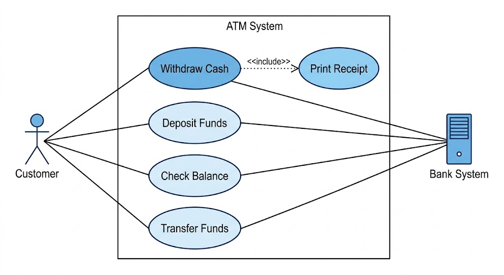
This foundational view helps stakeholders understand the system's purpose at a glance. The Customer actor initiates interactions, while the Bank System acts as a supporting external entity responsible for authorization and account management. Additional use cases like "Check Balance," "Transfer Funds," and "Change PIN" would typically surround the central "Withdraw Cash" function in a complete ATM specification.
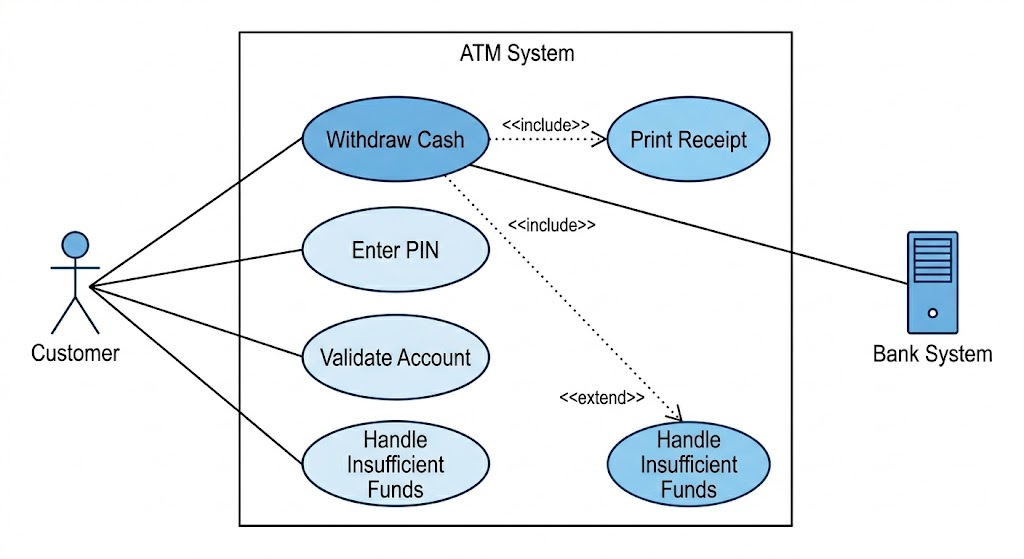
Next, we isolate the specific 'Withdraw Cash' use case to detail its relationships. This specialized diagram highlights essential sub-functions: it includes the mandatory 'User Authentication' and 'Print Receipt' steps, and extends to handle an alternative flow: 'Handle Insufficient Funds'.
Key modeling concepts demonstrated:
<> relationships: Represent mandatory sub-behaviors. Authentication and receipt printing are required for every successful withdrawal.
<> relationships: Model optional or conditional behavior. "Handle Insufficient Funds" only activates when the bank rejects the transaction due to balance constraints.
Actor specificity: The diagram clarifies which actor triggers or participates in each relationship, improving requirement traceability.
The relationships shown in the diagram above are defined precisely in the following table. This description maps the required steps and handling logic.
| Use Case ID | UC-01 |
|---|---|
| Use Case Name | Withdraw Cash |
| Actors | Customer (Initiator), Bank System (Supporting) |
| Description | Describes the process of a Customer using the ATM to withdraw funds from their linked bank account. |
| Pre-conditions | 1. The ATM is idle and displaying a welcome message.
2. The ATM has sufficient cash and paper supplies. |
| Post-conditions | Success: The Customer receives cash and a receipt; the account balance is updated.
Failure: The interaction is terminated; the card is returned; no funds are dispensed. |
| Included Use Cases | User Authentication (PIN Entry), Print Receipt (refer to image_1.png) |
| Main Success Scenario (Flow) | 1. Customer inserts their card.
2. System initiates User Authentication (Includes PIN handling). |
| Alternative Flows | A1: Insufficient Funds (Extension): In Step 7, if the Bank System reports insufficient funds, the system executes 'Handle Insufficient Funds' (refer to image_1.png), displays an error, offers a balance inquiry, and terminates the withdrawal.
A2: Incorrect PIN: Refer to User Authentication (not detailed here). |
This tabular format provides a single source of truth for developers, testers, and business stakeholders. Each field serves a specific purpose: pre/post-conditions define system state constraints, while the Main Success Scenario and Alternative Flows create a complete behavioral specification ready for implementation.
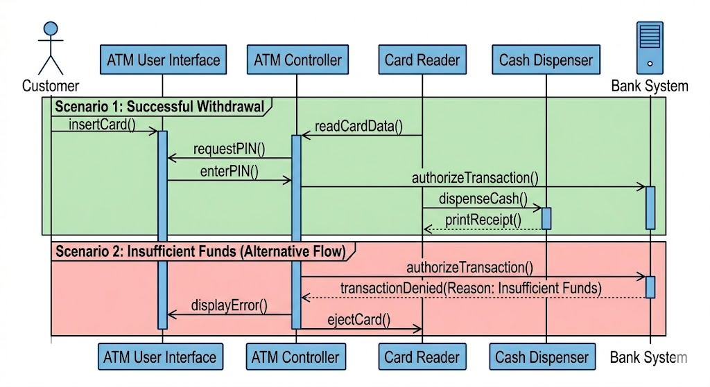
Finally, we operationalize the use case description using a Sequence Diagram. This image visualizes how the physical ATM components, the software controller, and the backend Bank System exchange messages over time. It explicitly details the Main Flow (Green) and the implementation of the extensions/alternatives (Red) defined in the previous steps.
Key elements illustrated:
Lifelines: Represent participating objects (Card Reader, UI, Transaction Controller, Bank Interface)
Activation bars: Show when each component is actively processing a request
Synchronous messages: Solid arrows denote request/response patterns requiring acknowledgment
Combined fragments: The alt frame cleanly separates the success path from the "Insufficient Funds" alternative
Return messages: Dashed arrows indicate completion and data flow back to the initiator
This diagram serves as both a design blueprint for developers and a validation tool for architects to verify that all use case requirements are technically feasible.
Visual Paradigm provides comprehensive support for UML modeling through a Use Case-centric approach. It allows you to model functional requirements via diagrams and then drill down into detailed behavioral specifications that can automatically generate further UML models like sequence diagrams.
Visual Paradigm supports all standard UML use case notations, including actors, use cases, and relationships such as <>, <>, and generalization.
AI-Powered Generation: You can generate complete use case diagrams by describing your system domain in natural language.
Structuring Tools: Features like the Resource Catalog allow you to quickly drag and create connected elements, while "packages" help organize large numbers of use cases.
Business Use Cases: Supports specific notations for business modeling, such as business actors and business use cases (marked with a slash).
Beyond simple shapes, Visual Paradigm includes a dedicated Use Case Description Editor to document the internal logic of a use case.
Flow of Events: A structured editor to list sequential steps of actor inputs and system responses.
Logic Operators: Supports business logic like if-then-else and loop operators directly within the textual description.
Supplementary Details: Fields are provided for ID, rank, status, preconditions, and postconditions.
Wireframe Integration: You can associate specific steps in a flow with wireframes to visualize the user interface at that exact moment.
Visual Paradigm treats sequence diagrams as a way to elaborate on the dynamic interactions defined in use cases.
Automated Generation: You can generate system-level sequence diagrams directly from the steps written in a use case's Flow of Events.
Modeling Features: Supports lifelines, activation bars, various message types (synchronous, asynchronous, recursive), and combined fragments for loops and alternatives.
Animation: Includes a feature to "run" or animate the sequence diagram to visualize how method calls and logic paths (like if-statements) execute.
Sub-diagrams: Allows you to create a sequence diagram as a sub-diagram of a use case to maintain strict traceability between requirements and design.
Modeling complex transactional systems like ATM cash withdrawals demands a disciplined, layered approach. By starting with high-level use case diagrams to establish scope, refining requirements through structured descriptions, and finally detailing interactions via sequence diagrams, teams can ensure alignment across business, design, and engineering disciplines.
Visual Paradigm accelerates this workflow by providing an integrated environment where requirements remain traceable, diagrams stay synchronized, and automation reduces manual overhead. The ATM "Withdraw Cash" example demonstrates how a single use case can evolve from a simple bubble on a diagram into a fully specified, technically actionable design artifact.
Whether you're documenting legacy system behavior or specifying new features for a digital banking platform, adopting this use case-driven methodology—supported by robust tooling—leads to clearer communication, fewer implementation surprises, and higher-quality software outcomes. Start with the user's goal, model the interactions rigorously, and let the diagrams guide your development with confidence.