The Unified Modeling Language (UML®) is a standardized visual modeling language created by the Object Management Group (OMG®). It enables teams to specify, visualize, construct, and document the architecture, structure, and behavior of software systems before writing a single line of code.
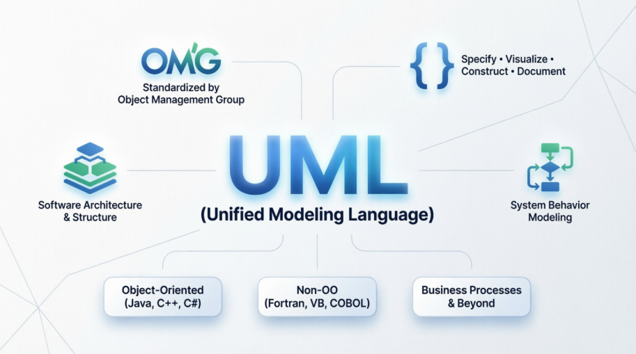
While originally designed for object-oriented systems (Java, C++, C#), UML is flexible enough to model:
Non-OO applications (Fortran, VB, COBOL)
Distributed systems across diverse middleware, OS, and hardware
Business processes, rules, and even non-software domains
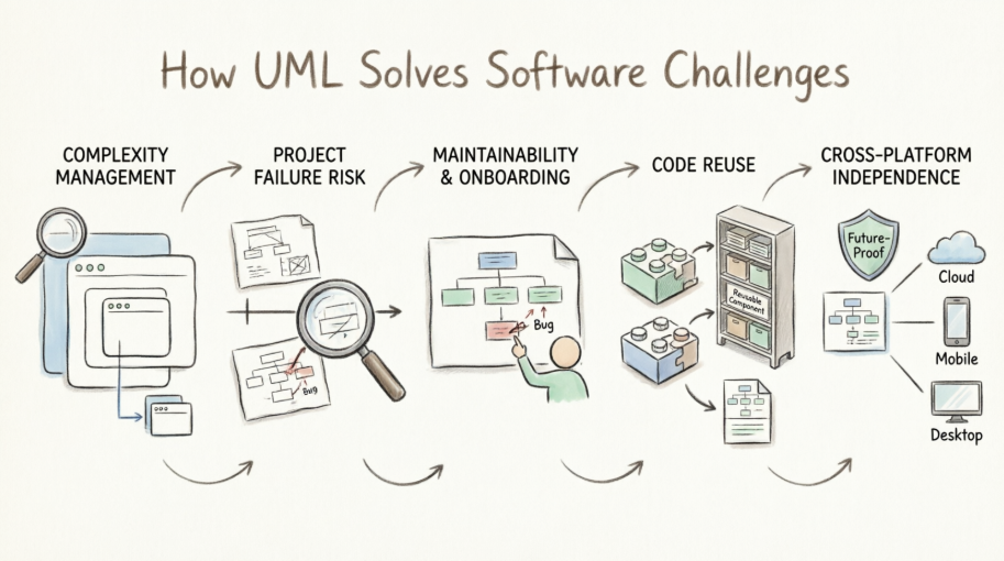
Modeling is to software what blueprints are to skyscrapers. It is essential because:
| Challenge | How UML Solves It |
|---|---|
| Complexity Management | Raises the level of abstraction, letting you zoom out to enterprise/environment views or zoom in to class/operation details. |
| Project Failure Risk | Large software projects historically fail more often than succeed. Modeling visualizes design against requirements before coding, catching flaws when changes are cheap. |
| Maintainability & Onboarding | Clearly defined architecture helps future maintenance programmers quickly locate, understand, and fix bugs long after original authors leave. |
| Code Reuse | Design-time structuring creates self-contained components. Enterprises build model/code libraries that can be imported into new projects instantly. |
| Cross-Platform Independence | UML models are middleware-agnostic. Combined with MDA (Model Driven Architecture), they future-proof applications against shifting technology stacks. |
UML 2.0 organizes diagrams into three categories:
| Category | Diagrams | Purpose |
|---|---|---|
| Structure (6) | Class, Object, Component, Composite Structure, Package, Deployment | Show static architecture: how parts are organized and connected |
| Behavior (3) | Use Case, Activity, State Machine | Show dynamic system behavior, workflows, and state transitions |
| Interaction (4) | Sequence, Communication, Timing, Interaction Overview | Detail how objects/components exchange messages over time |
Nested Classifiers: Embed classes inside components, or behaviors (state machines, activities) inside classes. Enables hierarchical, layered modeling (Enterprise → Site → Department → Application).
Improved Behavioral Modeling: All behavioral diagrams now derive from a unified behavior definition, creating consistency across models.
Structure-Behavior Linkage: Explicitly bind a behavior (e.g., a State Machine or Sequence) to the class or component that implements it.
Object Constraint Language (OCL) & Action Semantics: Built-in formalisms for specifying precise constraints and executable actions within models.
A methodology defines how you gather requirements, analyze them, and design the system. Examples vary by project size, domain (enterprise vs. embedded), and team structure.
✅ Guideline: OMG is methodology-neutral. Pick what fits your project first.
Most tools implement specific methodologies, but many support XMI® (XML Metadata Interchange) for cross-tool model portability.
✅ Guideline: Match tool capabilities to your methodology, budget, and project scale. Don't force a mismatch.
You and your team need training that covers:
UML fundamentals
Your chosen methodology
Your selected tool's workflow
Start high-level: Use Case & Package diagrams to capture scope & boundaries
Define structure: Class, Component, Deployment diagrams
Specify behavior: Activity, State Machine, Sequence diagrams
Refine & link: Use UML 2.0 nesting to embed behaviors inside structural elements
Validate against requirements before coding
| Guideline | Rationale |
|---|---|
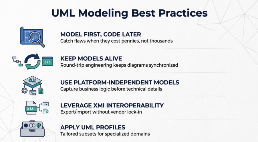
| Model First, Code Later | Catch architectural, scalability, security, and business-logic flaws when they cost pennies to fix, not thousands. |
| Keep Models Alive | Use tools that support round-trip engineering: generate code from models, and reverse-engineer code back into UML to keep diagrams synchronized. |
| Use Platform-Independent Models (PIMs) | Capture business functionality without technical implementation details. Transform to Platform-Specific Models (PSMs) only when ready for a target middleware/OS. |
| Leverage XMI for Interoperability | Export/import models between tools, repositories, or teams without vendor lock-in. |
| Apply UML Profiles for Specialized Domains | Use tailored subsets of UML for Real-Time, Transactional, or Fault-Tolerant systems instead of reinventing notation. |
🔹 Zoom Strategically: Use UML 2.0's nesting to toggle between enterprise-level architecture and class-level implementation. Don't put everything on one diagram.
🔹 Reverse-Engineer Legacy Systems: Feed existing source/object code into UML tools to generate diagrams. This reveals hidden dependencies, simplifies refactoring, and accelerates onboarding.
🔹 Execute Models Interpretively: Before coding, run your UML model in a tool to validate logic, workflows, and edge cases. You'll catch design gaps early.
🔹 Auto-Generate Code & Tests: Mature UML tools can produce deployable code (with transactional/database patterns baked in) and generate test/verification suites directly from models.
🔹 Don't Over-Model: UML is a communication and design tool, not a syntax exercise. Model only what adds value, reduces risk, or enables reuse.
🔹 Future-Proof with MDA: When new middleware or platforms emerge, OMG-standardized mappings allow you to regenerate cross-platform invocations or port entire applications from your existing PIMs.
🔹 Bridge Business & IT: Use Use Case and Activity diagrams during requirements gathering with stakeholders. Translate those directly into structural/behavioral models for developers.
Learn: Explore online tutorials or reference books (100+ titles exist for UML)
Specify: Download the official UML 2.0 specification from OMG (free, but highly technical)
Practice: Start with a small module. Model it → generate code/tests → iterate → scale to enterprise components
Standardize: Adopt XMI workflows and consider OMG certification for team-wide modeling consistency
💡 Final Takeaway: UML isn't about drawing perfect diagrams. It's about managing complexity, validating design before implementation, enabling reuse, and future-proofing architecture. When used intentionally alongside a sound methodology and modern tooling, UML dramatically increases the probability of delivering scalable, robust, and maintainable software on time and on budget.
Ready to put UML into practice? Here's a streamlined workflow to create your first professional diagram using Visual Paradigm:
Students & Hobbyists: Download the Community Edition for full-featured, non-commercial modeling.
Teams & Professionals: Start with the Online Edition for instant browser access, or evaluate Professional/Standard tiers for advanced collaboration and code engineering.
Not sure where to begin? Match your goal to the right UML diagram:
Designing system structure? → Class Diagram or Component Diagram
Mapping user interactions? → Use Case Diagram or Sequence Diagram
Documenting workflows? → Activity Diagram or State Machine Diagram
Exploring all options? Browse the Overview of the 14 UML Diagram Types
Visual Paradigm's intelligent editor helps you build syntactically correct diagrams:
Drag-and-drop elements from the palette
Connect objects with context-aware relationship lines
Use the AI Diagram Generator to sketch a diagram from a plain-English description like "Show a User class that can place Orders containing Products"
Run built-in model validation to catch design inconsistencies early
Toggle between diagram views to zoom from high-level architecture to detailed class operations
Export your model as PNG, PDF, or share via cloud link for stakeholder feedback
When you're ready to implement:
Generate skeleton code in Java, C#, Python, or other supported languages directly from your Class Diagram
Reverse-engineer existing codebases to visualize and document legacy systems
Keep design and implementation synchronized with round-trip engineering
💡 Pro Tip: Start small. Model one core feature end-to-end before scaling to enterprise-wide architecture. The UML Class Diagram Tutorial offers a hands-on walkthrough perfect for beginners.
UML Class Diagram Tutorial: Step-by-step tutorial for creating and understanding UML Class Diagrams for object-oriented design.
Free UML Tool: Download the forever-free Community Edition of Visual Paradigm for non-commercial UML modeling projects.
Overview of the 14 UML Diagram Types: Comprehensive reference explaining all standard UML 2.x diagram types and their use cases.
What is Class Diagram?: Foundational guide explaining the purpose, elements, and best practices for UML Class Diagrams.
A Comprehensive UML Modeling Solution: Blog post overviewing Visual Paradigm's capabilities for professional software development and system architecture.
UML Modeling Software Process and Tool: Guide covering the UML modeling workflow and how Visual Paradigm supports each stage.
UML Practical Guide: Step-by-step practical guidance for applying UML diagrams in real-world software projects.
AI-Powered UML Tool: Learn about Visual Paradigm's AI Diagram Generator that creates UML models from natural language descriptions.
UML Modeling User Guide: Official documentation for creating and managing UML diagrams within Visual Paradigm.
Code Engineering Tools: Explore round-trip engineering features for generating code from UML and reverse-engineering diagrams from source code.
Online UML Tool Features: Discover the capabilities of Visual Paradigm's web-based UML modeling platform.
Download Community Edition: Get the free forever Community Edition of Visual Paradigm for students and hobbyists.
Free Web-Based UML Software: Access Visual Paradigm Online for browser-based UML modeling with no installation required.
Free UML Design Tool: Learn about Visual Paradigm's free tools for creating professional UML designs and system architectures.
Free Online UML Tool: Web-based drag-and-drop UML modeling with no installation required, ideal for quick collaboration and prototyping.