
Visual Paradigm's AI-powered ecosystem transforms how teams create and maintain technical documentation by connecting conversational diagramming, structured C4 modeling, a centralized asset pipeline, and living documentation into one seamless workflow. This guide provides a comprehensive, step-by-step walkthrough of the complete workflow, from initial brainstorming to publishing living documentation, with extensive PlantUML examples and best practices.
Visual Paradigm's ecosystem consists of four interconnected AI pillars that work together to create a closed-loop workflow:
| Pillar | Purpose | When to Use |
|---|---|---|
| AI Visual Modeling Chatbot | Conversational ideation co-pilot; generates diagrams from natural language | Brainstorming, rapid prototyping, overcoming "blank canvas" syndrome |
| AI Apps & Studios (C4-PlantUML Studio) | Guided, methodology-driven modeling with step-by-step wizards | Structured refinement, C4 modeling, compliance, onboarding |
| OpenDocs | Living knowledge management platform with live, editable diagrams | Technical documentation, onboarding, stakeholder reports, wikis |
| VP Desktop | Professional precision modeling, validation, and code engineering | Enterprise architecture, semantic validation, code generation, traceability |
The Pipeline serves as the secure, cloud-hosted central transit hub that connects all five execution environments within the Visual Paradigm ecosystem. It enables teams to stream multi-source artifacts directly into unified technical documentation without manual file transfers or screenshots.
Key characteristics:
Cloud-hosted repository: Access artifacts from any device
Version-aware: Automatic revision tracking with commit notes
Editability preserved: Diagrams remain linked to source models, not static images
Role-based access: Configure permissions per project, team, or artifact
AI-integrated: Native support for AI-generated and AI-refined diagrams
The Five Execution Environments:
| Platform | Modeling Nature | Lifecycle & Versioning | Ideal Use Case |
|---|---|---|---|
| 1. AI Chatbot | Code-driven / Prompt-based | Static Snapshots | Rapid brainstorming, text-to-diagram generation |
| 2. Online Editor | Visual canvas-driven | Manual Tracking | Styling tweaks, collaborative browser-based editing |
| 3. OpenDocs | Consumer & Native Authoring | Live Link Insertion | Final documentation assembly, cross-referencing |
| 4. Desktop App | Model-driven & Validated | Automatic Revisions | Enterprise architecture, validated engineering models |
| 5. Web Apps (C4 Wizards) | Context-driven Wizards | Structural Architecture | Complex framework modeling, step-by-step guided design |
The C4 model, created by Simon Brown, is a hierarchical approach to visualizing software architecture across four levels:
| Layer | Purpose | Example |
|---|---|---|
| Context | Shows the system in its environment, including users and external systems | "E-commerce platform interacting with users, payment gateways, and inventory systems" |
| Container | Breaks the system into deployable units (apps, databases, microservices) | "Frontend (React), Backend (Node.js), Database (PostgreSQL)" |
| Component | Details internal modules and their interactions | "User Service, Order Service, Payment Processor" |
| Code (Optional) | Dives into class-level details | "UserRepository, OrderController" |
Dynamic views (Sequence, Deployment) complement the static structure, showing runtime behavior and infrastructure.
Goal: Transform a vague idea into a visual prototype in seconds.
Workflow:
Access the AI Chatbot via your Visual Paradigm workspace or chat.visual-paradigm.com
Prompt the AI using natural language describing your system or scenario:
"Generate a C4 System Context diagram for an e-commerce platform"
"Create a sequence diagram for our microservices authentication flow"
"Show me a use case diagram for a food delivery app"
Review and refine iteratively using follow-up commands:
"Add an admin actor who can reset passwords"
"Insert a retry loop if OTP validation fails (max 3 attempts)"
"Show parallel messages: after payment success, notify customer and update inventory simultaneously"
Export to Pipeline: Click the Export icon → Select Send to OpenDocs Pipeline
Add Metadata: Include descriptive comments like "Baseline auth flow draft – Q2 2026" for version identification
💡 Pro Tip: Use the Chatbot for rapid iteration on early-stage concepts. Once a diagram stabilizes, migrate it to Desktop for semantic validation and automated sync.
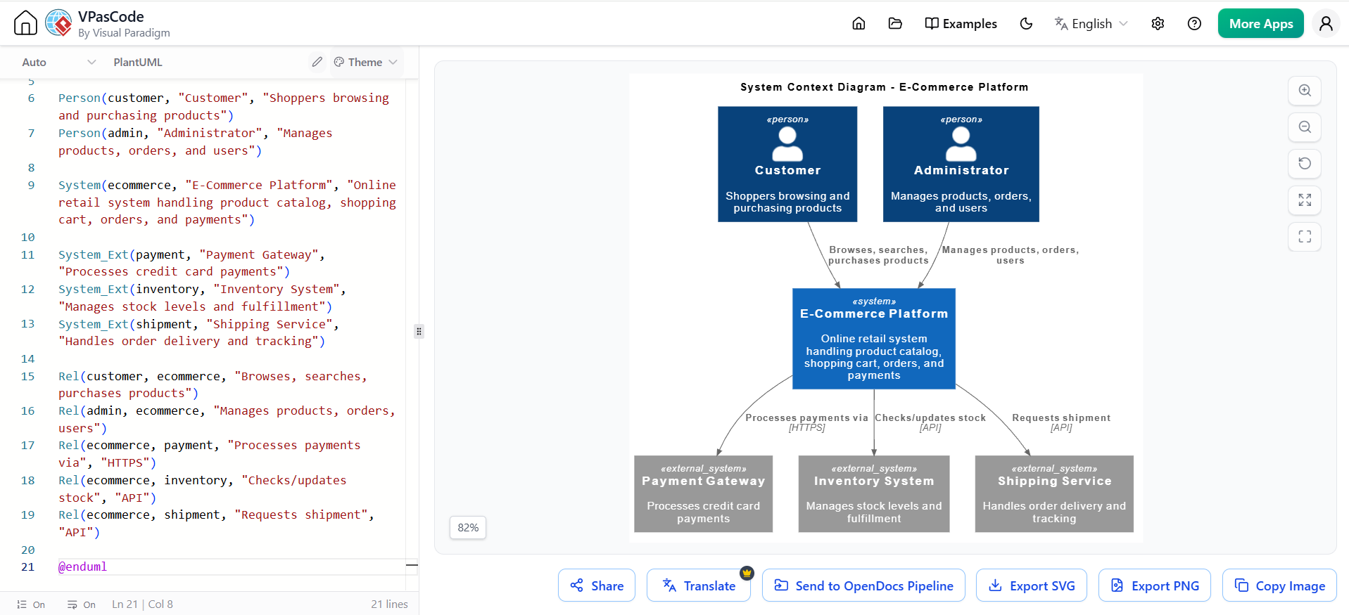
@startuml
!include https://raw.githubusercontent.com/plantuml-stdlib/C4-PlantUML/master/C4_Context.puml

title System Context Diagram - E-Commerce Platform

Person(customer, "Customer", "Shoppers browsing and purchasing products")
Person(admin, "Administrator", "Manages products, orders, and users")

System(ecommerce, "E-Commerce Platform", "Online retail system handling product catalog, shopping cart, orders, and payments")

System_Ext(payment, "Payment Gateway", "Processes credit card payments")
System_Ext(inventory, "Inventory System", "Manages stock levels and fulfillment")
System_Ext(shipment, "Shipping Service", "Handles order delivery and tracking")

Rel(customer, ecommerce, "Browses, searches, purchases products")
Rel(admin, ecommerce, "Manages products, orders, users")
Rel(ecommerce, payment, "Processes payments via", "HTTPS")
Rel(ecommerce, inventory, "Checks/updates stock", "API")
Rel(ecommerce, shipment, "Requests shipment", "API")

@enduml
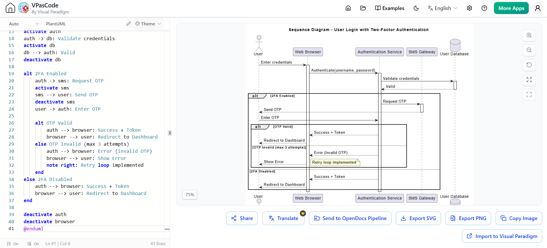
@startuml
title Sequence Diagram - User Login with Two-Factor Authentication

actor "User" as user
participant "Web Browser" as browser
participant "Authentication Service" as auth
participant "SMS Gateway" as sms
database "User Database" as db

user -> browser: Enter credentials
activate browser
browser -> auth: Authenticate(username, password)
activate auth
auth -> db: Validate credentials
activate db
db --> auth: Valid
deactivate db

alt 2FA Enabled
    auth -> sms: Request OTP
    activate sms
    sms --> user: Send OTP
    deactivate sms
    user -> auth: Enter OTP

    alt OTP Valid
        auth --> browser: Success + Token
        browser --> user: Redirect to Dashboard
    else OTP Invalid (max 3 attempts)
        auth --> browser: Error (Invalid OTP)
        browser --> user: Show Error
        note right: Retry loop implemented
    end
else 2FA Disabled
    auth --> browser: Success + Token
    browser --> user: Redirect to Dashboard
end

deactivate auth
deactivate browser
@enduml
Goal: Evolve the AI-generated sketch into a complete, standards-compliant C4 model.
Workflow:
Launch the C4 Architecture Guide from the Web Apps menu
Define the Problem Statement – Use AI Assist to generate a full description:
Project name
System purpose
Primary users
Key integrations
Generate Each C4 Layer Step-by-Step:
Level 1 – System Context: Input system boundaries, external users, and dependent systems
Level 2 – Containers: Configure deployable applications, databases, and external services
Level 3 – Components: Refine internal code modules and their interactions
Level 4 – Code (optional): Map to actual code structures
Add Supporting Views:
Dynamic/Sequence Diagrams: Show runtime interactions
Deployment Diagrams: Map software to infrastructure
Landscape Diagrams: Show system in broader enterprise context
Stream to Pipeline: Click Stream Structure to Pipeline to export the entire hierarchical model block
🎯 Use Case: Ideal for architecture review boards, onboarding documentation, and stakeholder presentations where multi-layer clarity is essential.
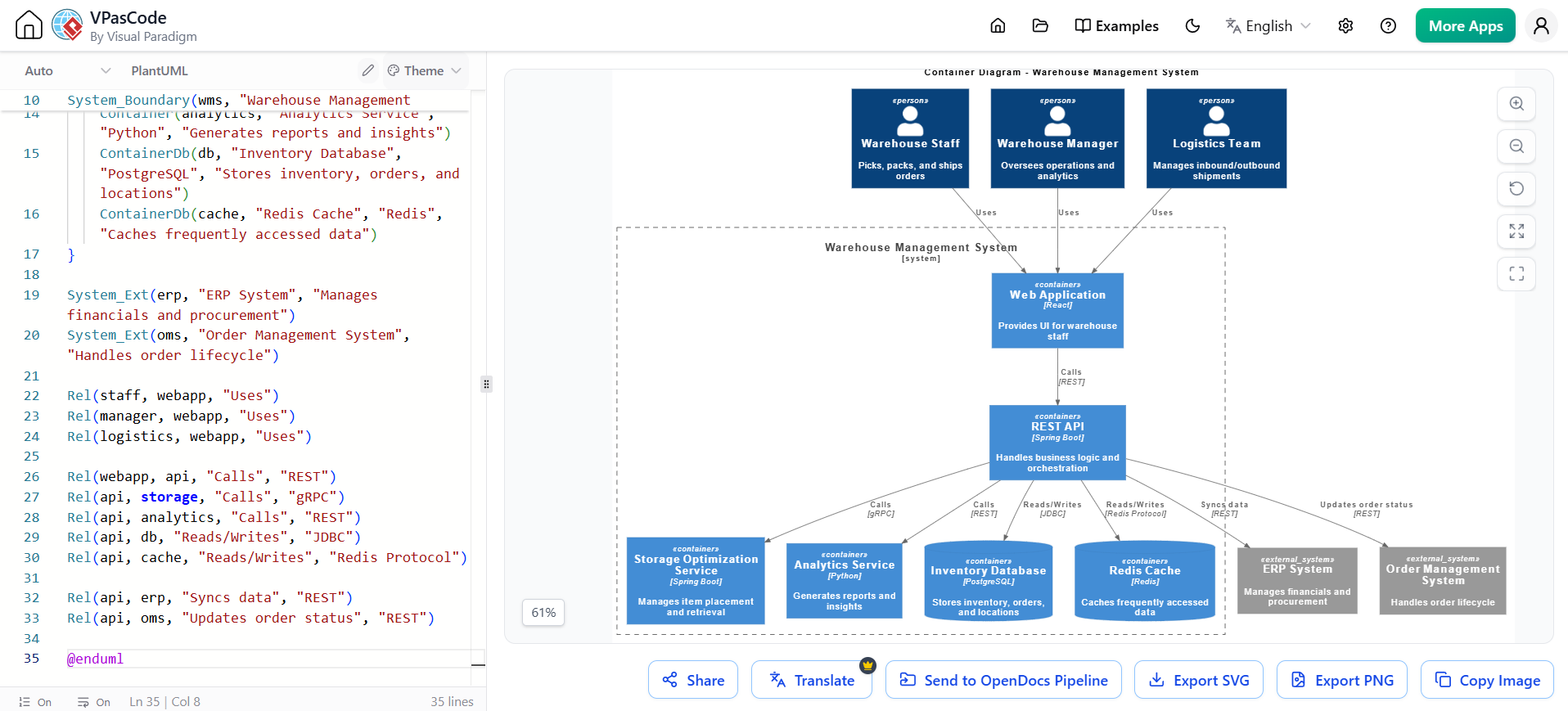
@startuml
!include https://raw.githubusercontent.com/plantuml-stdlib/C4-PlantUML/master/C4_Container.puml

title Container Diagram - Warehouse Management System

Person(staff, "Warehouse Staff", "Picks, packs, and ships orders")
Person(manager, "Warehouse Manager", "Oversees operations and analytics")
Person(logistics, "Logistics Team", "Manages inbound/outbound shipments")

System_Boundary(wms, "Warehouse Management System") {
    Container(webapp, "Web Application", "React", "Provides UI for warehouse staff")
    Container(api, "REST API", "Spring Boot", "Handles business logic and orchestration")
    Container(storage, "Storage Optimization Service", "Spring Boot", "Manages item placement and retrieval")
    Container(analytics, "Analytics Service", "Python", "Generates reports and insights")
    ContainerDb(db, "Inventory Database", "PostgreSQL", "Stores inventory, orders, and locations")
    ContainerDb(cache, "Redis Cache", "Redis", "Caches frequently accessed data")
}

System_Ext(erp, "ERP System", "Manages financials and procurement")
System_Ext(oms, "Order Management System", "Handles order lifecycle")

Rel(staff, webapp, "Uses")
Rel(manager, webapp, "Uses")
Rel(logistics, webapp, "Uses")

Rel(webapp, api, "Calls", "REST")
Rel(api, storage, "Calls", "gRPC")
Rel(api, analytics, "Calls", "REST")
Rel(api, db, "Reads/Writes", "JDBC")
Rel(api, cache, "Reads/Writes", "Redis Protocol")

Rel(api, erp, "Syncs data", "REST")
Rel(api, oms, "Updates order status", "REST")

@enduml
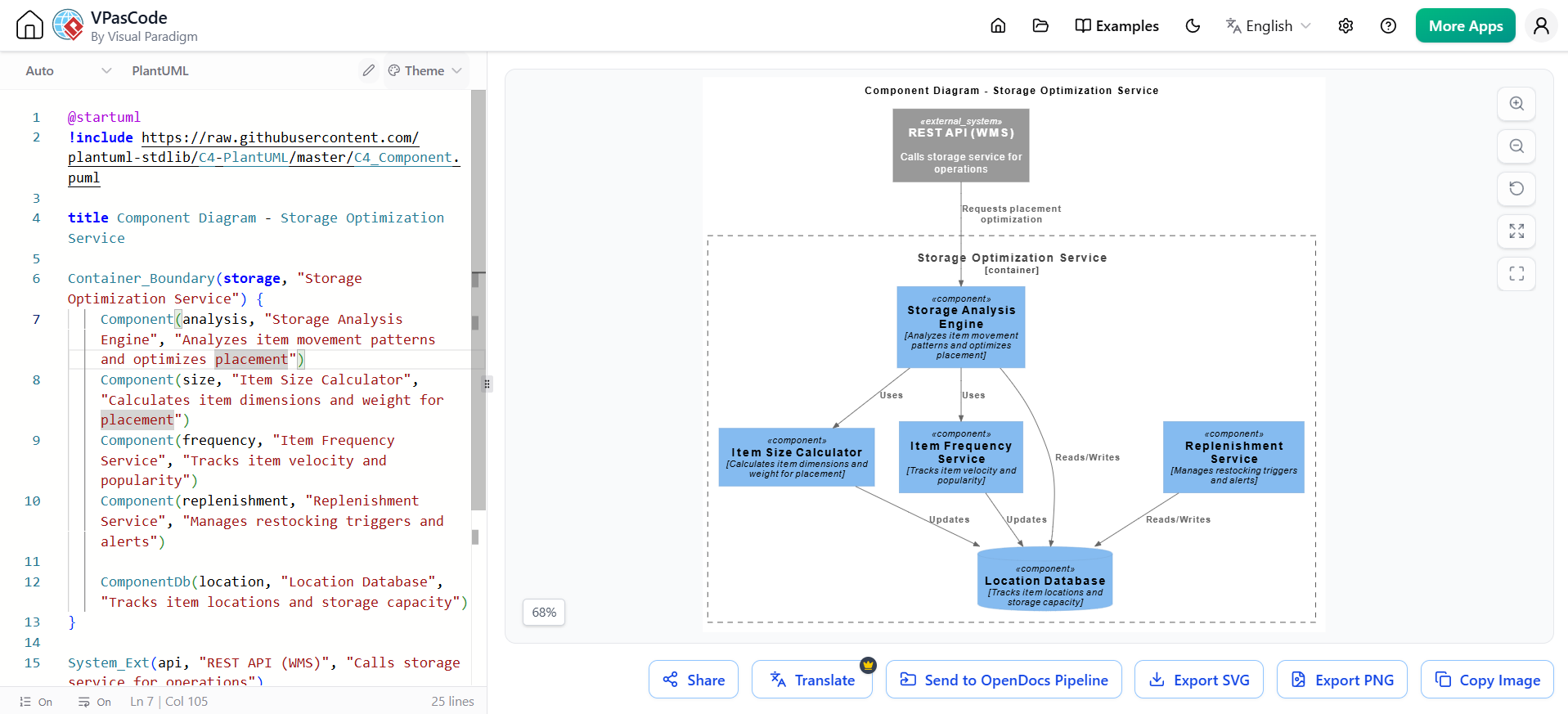
@startuml
!include https://raw.githubusercontent.com/plantuml-stdlib/C4-PlantUML/master/C4_Component.puml

title Component Diagram - Storage Optimization Service

Container_Boundary(storage, "Storage Optimization Service") {
    Component(analysis, "Storage Analysis Engine", "Analyzes item movement patterns and optimizes placement")
    Component(size, "Item Size Calculator", "Calculates item dimensions and weight for placement")
    Component(frequency, "Item Frequency Service", "Tracks item velocity and popularity")
    Component(replenishment, "Replenishment Service", "Manages restocking triggers and alerts")

    ComponentDb(location, "Location Database", "Tracks item locations and storage capacity")
}

System_Ext(api, "REST API (WMS)", "Calls storage service for operations")

Rel(api, analysis, "Requests placement optimization")
Rel(analysis, size, "Uses")
Rel(analysis, frequency, "Uses")
Rel(analysis, location, "Reads/Writes")
Rel(size, location, "Updates")
Rel(frequency, location, "Updates")
Rel(replenishment, location, "Reads/Writes")

@enduml
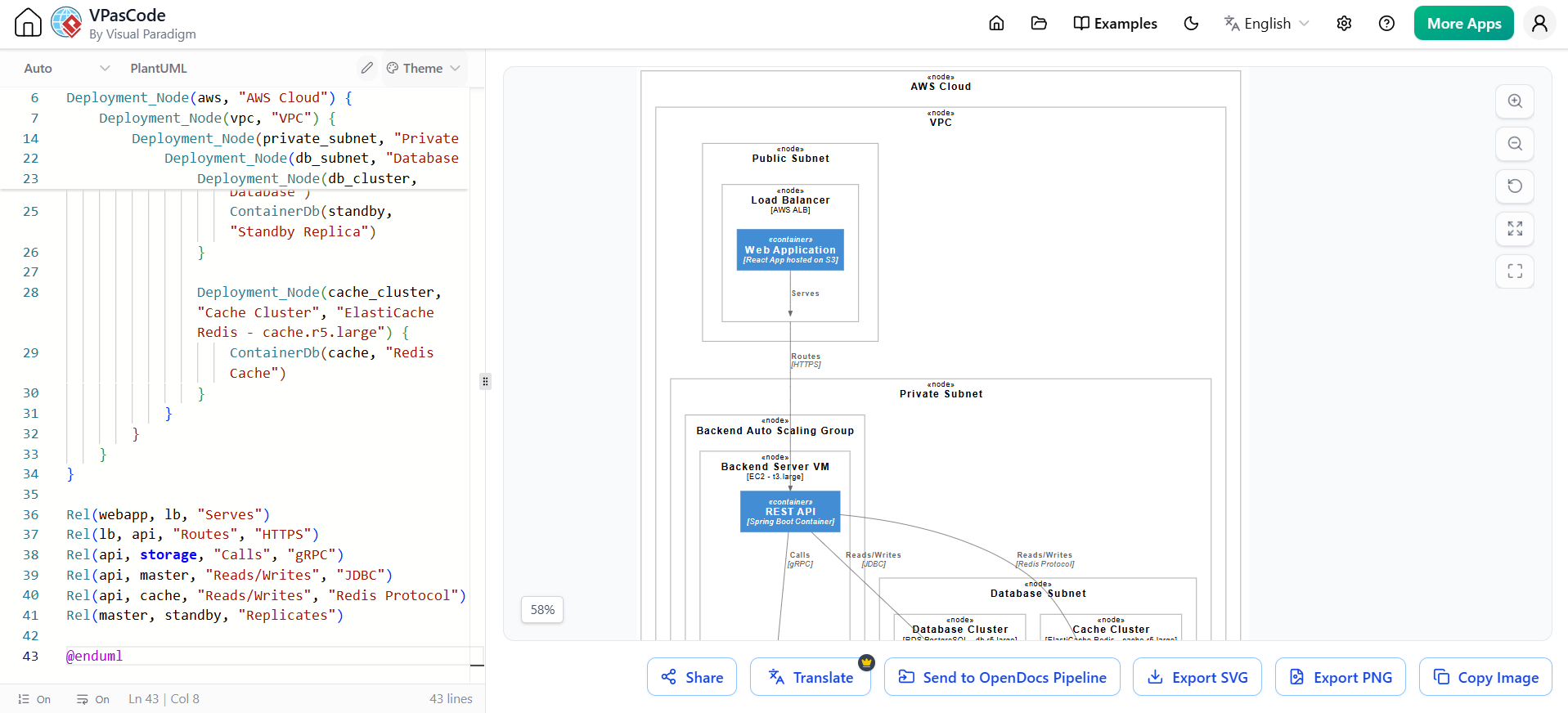
@startuml
!include https://raw.githubusercontent.com/plantuml-stdlib/C4-PlantUML/master/C4_Deployment.puml

title Deployment Diagram - Warehouse Management System

Deployment_Node(aws, "AWS Cloud") {
    Deployment_Node(vpc, "VPC") {
        Deployment_Node(public_subnet, "Public Subnet") {
            Deployment_Node(lb, "Load Balancer", "AWS ALB") {
                Container(webapp, "Web Application", "React App hosted on S3")
            }
        }

        Deployment_Node(private_subnet, "Private Subnet") {
            Deployment_Node(backend_asg, "Backend Auto Scaling Group") {
                Deployment_Node(backend_vm, "Backend Server VM", "EC2 - t3.large") {
                    Container(api, "REST API", "Spring Boot Container")
                    Container(storage, "Storage Optimization", "Spring Boot Container")
                }
            }

            Deployment_Node(db_subnet, "Database Subnet") {
                Deployment_Node(db_cluster, "Database Cluster", "RDS PostgreSQL - db.r5.large") {
                    ContainerDb(master, "Primary Database")
                    ContainerDb(standby, "Standby Replica")
                }

                Deployment_Node(cache_cluster, "Cache Cluster", "ElastiCache Redis - cache.r5.large") {
                    ContainerDb(cache, "Redis Cache")
                }
            }
        }
    }
}

Rel(webapp, lb, "Serves")
Rel(lb, api, "Routes", "HTTPS")
Rel(api, storage, "Calls", "gRPC")
Rel(api, master, "Reads/Writes", "JDBC")
Rel(api, cache, "Reads/Writes", "Redis Protocol")
Rel(master, standby, "Replicates")

@enduml
Goal: Transform the initial C4 model into a precise, maintainable architecture with proper relationships.
Key Relationship Patterns:
| Relationship | Purpose | Example |
|---|---|---|
| «include» | Mandatory shared behavior reused across use cases | "Book a Table" includes "Process Payment" |
| «extend» | Optional or conditional behavior | "Apply Discount" extends "Book a Table" when promo code entered |
| Generalization | Inheritance between actors or use cases | "Admin" inherits from "User" |
AI-Suggested Refinements:
Commonality Extraction: Identifying redundant steps → suggest «include» relationships
Conditional Logic Branching: Detecting "if-then" scenarios → suggest «extend» relationships
Actor Generalization: Finding overlapping responsibilities → suggest hierarchy
Complexity Decomposition: Identifying overly large use cases → break into sub-diagrams
Key Insight: The AI removes the mechanical work of drawing arrows and spotting patterns, while your domain knowledge ensures relationships make real business sense.
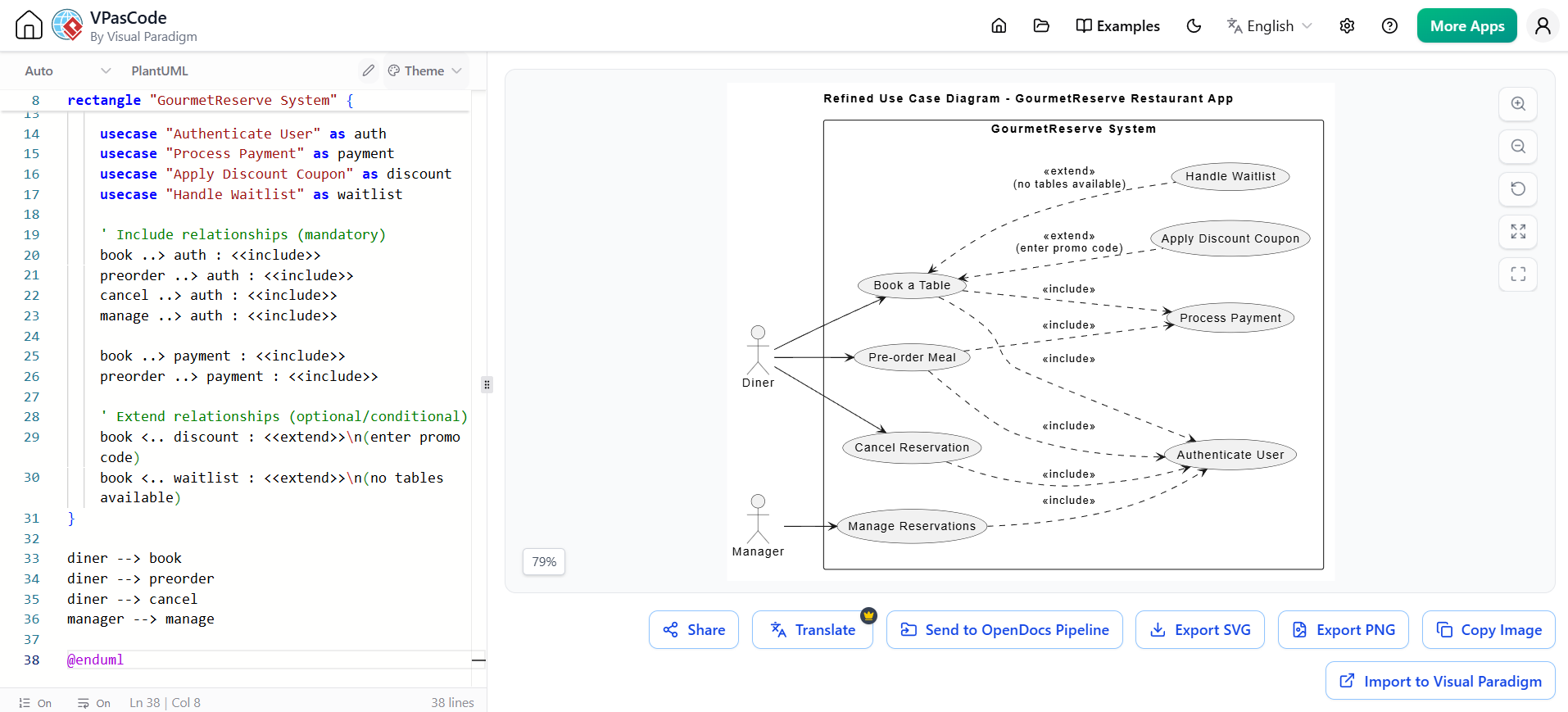
@startuml
title Refined Use Case Diagram - GourmetReserve Restaurant App

left to right direction
actor "Diner" as diner
actor "Manager" as manager

rectangle "GourmetReserve System" {
    usecase "Book a Table" as book
    usecase "Pre-order Meal" as preorder
    usecase "Cancel Reservation" as cancel
    usecase "Manage Reservations" as manage

    usecase "Authenticate User" as auth
    usecase "Process Payment" as payment
    usecase "Apply Discount Coupon" as discount
    usecase "Handle Waitlist" as waitlist

    ' Include relationships (mandatory)
    book ..> auth : <<include>>
    preorder ..> auth : <<include>>
    cancel ..> auth : <<include>>
    manage ..> auth : <<include>>

    book ..> payment : <<include>>
    preorder ..> payment : <<include>>

    ' Extend relationships (optional/conditional)
    book <.. discount : <<extend>>\n(enter promo code)
    book <.. waitlist : <<extend>>\n(no tables available)
}

diner --> book
diner --> preorder
diner --> cancel
manager --> manage

@enduml
Goal: Compile and publish living documentation where diagrams auto-update when source models change.
Workflow:
Open your technical manual in the OpenDocs document editor
Position cursor at the desired insertion point
Insert Pipeline Artifact:
Toolbar → Insert → Pipeline (left sidebar)
Browse the shared team collection
Filter by comment, date, or source platform
Render inline: The diagram appears instantly with full resolution and interactive capabilities
Write surrounding context using Markdown with live preview:
Rich text editing
Tables, code blocks, hierarchical folders
All while diagrams stay interactive
Manage Updates:
A floating Revision Indicator (🔄) appears next to embedded diagrams when newer Pipeline versions exist
Click the indicator to view chronological timestamps, commit notes, and source platform side-by-side
Swap versions to update your master document instantly
Previous versions remain accessible for audit trails or rollback scenarios
💡 Key Concept: Unlike standard text platforms where images are static snapshots, embedded visuals in OpenDocs remain live vectors. Users can click the element directly inside the document to open the source model and update it.
📁 Project Documentation
├── 📄 01 - Executive Summary
│   └── [AI-Generated Stakeholder Summary with System Context Diagram]
├── 📄 02 - Architecture Overview
│   ├── [C4 Context Diagram - Live]
│   ├── [C4 Container Diagram - Live]
│   └── Technology Stack Decisions
├── 📄 03 - Detailed Design
│   ├── [Component Diagrams - Live]
│   ├── [Sequence Diagrams - Live]
│   └── API Specifications
├── 📄 04 - Deployment Architecture
│   ├── [Deployment Diagram - Live]
│   └── Infrastructure Requirements
└── 📄 05 - Quality Assurance
    ├── [Test Cases from AI Generator]
    └── Coverage Metrics
Goal: Automatically generate traceable test cases from your models.
AI-Generated Test Assets:
| Test Artifact | Source | Example |
|---|---|---|
| Test Cases | Use case specifications, decision tables, Activity/Sequence Diagrams | TC-001 – Happy Path, TC-002 – Payment Failure |
| Preconditions | Use case flows | "Diner logged in, tables available, party size 4" |
| Traceability Links | Requirements to design elements to test cases | "Trace: Main flow steps 1–7, Decision Table Rule R1" |
| Coverage Metrics | Project Dashboard | "92% of decision table rules tested" |
Example AI-Generated Test Cases:
TC-001 – Happy Path – No Deposit Required
Priority: High
Preconditions: Diner logged in (Gold loyalty), tables available, non-peak hours, party size 4
Steps:
  1. Search tables → select slot
  2. Review summary (no deposit shown)
  3. Confirm booking
Expected: Reservation confirmed, confirmation sent, no payment screen
Trace: Main flow steps 1–7, Decision Table Rule R1

TC-002 – Deposit Required – Payment Fails
Priority: High
Preconditions: Party size 10, peak hours, non-Gold, valid card but insufficient funds
Steps:
  1. Select slot → proceed to payment
  2. Enter card → submit
Expected: Error message "Payment declined", booking not created, return to slot selection
Trace: Decision Table Rule R5, Exception flow 4b
Goal: Maintain a single source of truth across all artifacts.
The Closed-Loop Workflow:
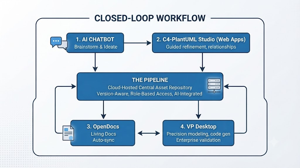
Bidirectional Sync Benefits:
Update a class in Desktop → refreshes in OpenDocs automatically
Refine a prompt in the Chatbot → push changes back to Studios
Single-account synchronization
Version history and full traceability
Zero manual rework
Effective Prompting Techniques:
| Do | Don't |
|---|---|
| Name participants clearly upfront: "User, Browser, AuthService" | Vague requests like "Make a system diagram" |
| Use control-flow language: "if...then...else", "while", "in parallel" | Assume AI knows architectural layers you haven't mentioned |
| Specify architectural layers: "Controller → Service → Repository" | Mix multiple unrelated scenarios in one prompt |
| Request annotations: "Add notes for preconditions" | Expect perfect layout on first attempt |
| Ask for variations: "Show failure path separately" | Forget to iterate and refine |
Iterative Refinement Commands:
"Add a retry loop if OTP validation fails (max 3 attempts)"
"Insert two-factor step only if user has 2FA enabled (use opt fragment)"
"Show parallel messages: after payment success, notify customer and update inventory simultaneously"
"Change the PaymentGateway lifeline to show a timeout after 30 seconds"
"Add a self-message on OrderService to calculate total before calling PaymentGateway"
Layer-Specific Guidelines:
| Layer | Best Practice |
|---|---|
| Context | Show only the system boundary and immediate external interactions; one box for the entire system |
| Container | Show deployable units (applications, databases, services); avoid showing technology details in relationships |
| Component | Show logical grouping of classes; ensure each component has a clear responsibility |
| Deployment | Map components to actual infrastructure; include redundancy and scaling information |
General C4 Principles:
Each level should provide a different perspective, not just more detail
Diagrams should be self-explanatory with minimal text
Maintain consistency of terminology across all levels
Use color coding to differentiate system vs. external components
Metadata Management:
| Practice | Why |
|---|---|
| Add descriptive commit notes | Aid version identification and audit trails |
| Use consistent naming conventions | Enable filtering and search across team collection |
| Include source platform info | Track artifact provenance |
| Tag with sprint or release identifiers | Facilitate rollback and comparison |
Version Management:
Review revisions before swapping in documents
Keep previous versions accessible for audit trails
Use the Revision Indicator (🔄) to identify outdated diagrams
Batch updates when possible to maintain document coherence
Documentation Structure:
| Practice | Description |
|---|---|
| Use Tree-Structured Spaces | Organize documentation using hierarchical nested folders; mirror system architecture |
| Embed, Don't Attach | Insert live Pipeline artifacts instead of static screenshots |
| Maintain Separation of Concerns | Separate architecture diagrams from detailed implementation docs |
| Enable Collaboration | Share single links; stakeholders comment directly on diagrams or text |
JIT (Just-in-Time) Embedding Pathways:
Ad Hoc Embedding: Click Insert > Diagram directly within a document page
AI-Driven Generation: Use natural language to create diagrams inside the text narrative
Central Asset Pipeline: Push from Desktop/Online to Pipeline; pull into documents
Traceability Requirements:
| Artifact | Traceability Requirement |
|---|---|
| Use Cases | Link to requirements and test cases |
| Decision Tables | Ensure every rule covered by at least one test |
| Activity/Sequence Diagrams | Link test steps to specific diagram elements |
| Non-functional aspects | Include in notes or constraints; test separately |
Test Coverage Metrics:
Monitor completeness via Project Dashboard
Track coverage across: use cases, decision tables, scenarios (happy path, alternatives, exceptions, boundary cases)
Risk-based prioritization of remaining test cases
AI-Generated Report Structure:
| Section | Content |
|---|---|
| Executive Summary | High-level narrative of system goals |
| Visual Logic Models | Rendered Use Case, Activity, and Sequence Diagrams |
| Functional Specifications | Detailed flow of events (Main, Alternative, Exception paths) |
| Traceability Matrix | Requirements → Design → Test Cases |
| Data Schema | Entity-Relationship Diagrams and class structures |
| Deployment Plan | Infrastructure requirements and topology |
Step 1: AI Chatbot - Ideation
Prompt: "Create a C4 System Context diagram for a Warehouse Management System
that integrates with ERP and Order Management"
Output: Initial Context diagram showing users (Warehouse Staff, Manager, Logistics) and external systems (ERP, OMS).
Step 2: C4-PlantUML Studio - Guided Refinement
Define problem statement with AI Assist
Generate Container Diagram: Web App (React), Storage Optimization Service (Spring Boot), Inventory Database (PostgreSQL)
Generate Component Diagram: Storage Analysis Engine, Item Size Calculator, Item Frequency Service, Replenishment Service
Generate Deployment Diagram: AWS architecture with EC2, RDS, ElastiCache
Add Dynamic Views: Sequence diagrams for inventory movement tracking
Step 3: Relationship Refinement
AI identifies and suggests:
«include» → Authenticate User for all use cases
«include» → Process Payment for Book a Table and Pre-order Meal
«extend» → Apply Discount Coupon (conditional on promo code)
«extend» → Handle Waitlist (conditional on no tables available)
Step 4: OpenDocs - Living Documentation
Insert all Pipeline artifacts into documentation pages
Write Markdown explanations with embedded live diagrams
Add test cases automatically generated from use cases and decision tables
Publish to stakeholder portal via secure sharing link
Step 5: Synchronization
Two weeks later, engineering alters the storage optimization algorithm
Architect edits the diagram in VP Desktop
OpenDocs flags sync change to authoring team
Team swaps to new revision without breaking manual formatting
All stakeholders see updated documentation immediately
Visual Paradigm's AI ecosystem transforms fragmented "Concept-to-Docs" workflows into a unified automated pipeline where visual models and documentation evolve together as a single source of truth.
Key Benefits:
| For Technical Teams | For Business Stakeholders | For Organizations |
|---|---|---|
| Reduced maintenance overhead | Better understanding of complex systems | Single source of truth |
| Improved accuracy | Faster decision-making | Eliminated information silos |
| Enhanced collaboration | Reduced risk of miscommunication | Scalable knowledge management |
| AI-powered efficiency | Up-to-date information always available | Future-proof publishing |
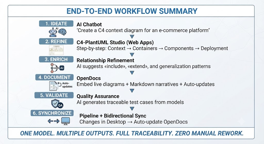
| Task | Tool | Why |
|---|---|---|
| Brainstorming and rapid prototyping | AI Chatbot | Fastest way from idea to visual |
| Structured C4 modeling | C4-PlantUML Studio | Guided workflows ensure completeness |
| Living documentation | OpenDocs | Diagrams auto-update; single source of truth |
| Precision engineering | VP Desktop | Validation, code generation, enterprise features |
| Test case generation | AI Use Case Studio | From use cases and decision tables to test assets |
| Reporting | AI Reporting | Executive summaries, technical guides, audit trails |
!include https://raw.githubusercontent.com/plantuml-stdlib/C4-PlantUML/master/C4_Context.puml
Person(user, "User", "Description")
System(system, "System Name", "Description")
System_Ext(external, "External System", "Description")
Rel(user, system, "Uses", "Protocol")
!include https://raw.githubusercontent.com/plantuml-stdlib/C4-PlantUML/master/C4_Container.puml
Container(container, "Container Name", "Technology", "Description")
ContainerDb(db, "Database", "PostgreSQL", "Stores data")
!include https://raw.githubusercontent.com/plantuml-stdlib/C4-PlantUML/master/C4_Component.puml
Component(component, "Component Name", "Description")
!include https://raw.githubusercontent.com/plantuml-stdlib/C4-PlantUML/master/C4_Deployment.puml
Deployment_Node(node, "Node Name", "Technology")
actor "Actor Name" as actor
participant "Participant" as participant
actor -> participant: Message
activate participant
participant --> actor: Return
deactivate participant
actor "User" as user
usecase "Use Case" as uc
user --> uc
uc ..> included : <<include>>
uc <.. extended : <<extend>>
This guide provides a comprehensive foundation for implementing the Visual Paradigm AI Chatbot + C4 + Pipeline + OpenDocs workflow. Start with the AI Chatbot for ideation, use C4-PlantUML Studio for structured refinement, and complete the loop with OpenDocs for living documentation that automatically stays synchronized with your evolving architecture.

