Deployment Diagram describes what existing systems will system need to interact or integrate with, such as:
- What and who will connect to or interact with system, and how will they do it?
- What middle-ware, including the operating system and communications approaches and protocols, will system use?
- What hardware and software will users directly interact with (PCs, network computers, browsers, etc.)?
How to develop Deployment Diagrams?
The steps below outline the major steps to take in creating a UML Deployment Diagram.
- Decide on the purpose of the diagram
- Add nodes to the diagram
- Add communication associations to the diagram
- Add other elements to the diagram, such as components or active objects, if required
- Add dependencies between components and objects, if required
Developing a Deployment Diagram
- Click Diagram > New from the toolbar.

- In the New Diagram window, choose Deployment Diagram then click Next. The search bar can help you searching the diagram.

- Name the diagram, then click OK. In this tutorial, we will name the diagram Deployment Diagram Tutorial.

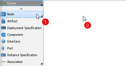
- To create the first node, choose Node from the menu on the left, then click on any empty space on the diagram. Rename the node by double clicking the name.

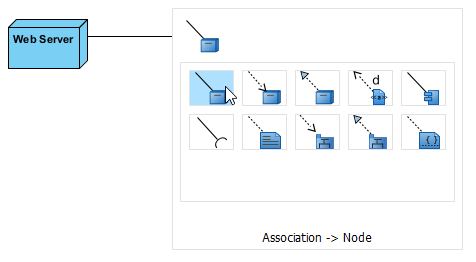
- To create a node which associates with other nodes, click on the node (Web Server in this case), then click drag the resource icon Resource Catalog.

When you release the cursor, a popup menu will appear. Select Association -> Node form the menu, a new node will be created.

- Repeat step 5 to generate more nodes.
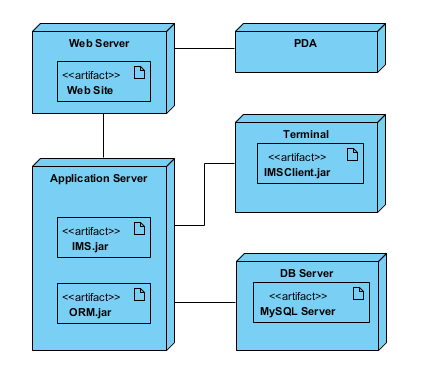
- To create an artifact for a node, click Artifact from the menu on the left, then click the desire node. Rename the artifact by double clicking the name.

- Repeat step 7 for more artifacts.
- You should have a diagram similar to this:


