In/Out Flows in sub-diagram
Diagrams types like Business Process Diagram (BPD), (UML) State Machine Diagram and (UML) Activity Diagram are mainly for modeling 'flows'. You draw BPD for representing business workflow, state machine diagarm for representing state transition and activity diagram for representing flow of system actions.When you create sub-diagrams from these diagram types, you probably want the flow to continue flowing from the parent diagram to sub-diagram and from the sub-diagram back to the parent diagram. In order to keep the flow flows, you can make use of the in and out flow objects in sub-diagram.
|
|
| In Flow and Out Flow objects in a sub-diagram (BPD Example) |
Instead of creating one yourself, the in/out flow objects will be created for you automatically in the following situations:
- Business Process Diagram - Creating a sub process BPD from a Sub-Process
- State Machine Diagram - Creating a sub state machine (diagram) from an Submachine state
- Actiivty Diagram - Creating Activity/State Machine as the 'behavior' of an Action
By performing any of these steps, you will see the in/out flow objects in the sub-diagarm, provided that a flow exist.
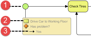
Reading In/Out Flows
 |
| An in flow |
|
||||||||
| Description of an in flow |
Modeling with In/Out Flows
To represent that a flow flows from the parent diagarm to content in sub-diagarm, simply connect the initial node with the sub-diagarm content. When the flow ends, connect the final element with the end node.
Hiding/Showing In/Out Flows
To hide in/out flows in sub-diagram, right click on it and select Hide In/Out Flows from the popup menu.
 |
| Hiding In and Out Flows |
Going back to the parent diagram
To go back to the parent diagram, simply click on the model element link inside the in/out flow, like this:
 |
| Go back to parent diagram |
Related Resources
The following resources may help you to learn more about the topic discussed in this page.
| 5. Showing model indicator | Table of Contents | Chapter 8. Using shape editor |

