Incorporating user stories in system design
Visual Paradigm allows you to write and manage user stories. Besides writing user stories in UeXceler, you can also write user stories on any diagrams, like BPD. To write user stories in diagrams lets you relate user’s concern or requirements, as represented by story cards, with system designs. In particular, the visual mapping between user stories and BPMN activities provides you with a way to identify user stories based on a business process (diagram).
Writing user story in a diagram
- Open the diagram where you want to wite user story.
- Select User Story from the diagram toolbar.

Selecting user story - Click on the diagram to create a story card.

Creating a user story card on diagram - Enter the name of user story and press Enter to confirm editing. You may also click on the background of diagram for confirmation.

User story created
| NOTE: | Once a user story is created in diagram, you can view and manage it in UeXceler. |
Use case based user story
User stories can be written in use case basis. By writing a user story in a sub-diagram of a use case, the story will be placed under that use case, as seen in UeXceler.
Relating user story with a shape
- Move your mouse pointer over the story card.
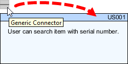
- Press on the Generic Connector resource and drag it out.

Using generic connector - Release the mouse button on the target shape to create the connector.

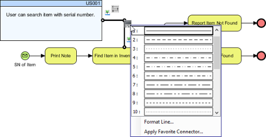
User story connected with BPMN task - If you find it difficult to differentiate the connector with other connectors on diagram, you can configure the connector style to make it look different. Simply click on the connector, click on the Format Line resource and select a style you want.

To select a connector style
Related Resources
The following resources may help you learn more about the topic discussed in this page.
| 16. Tracing changings of a user story | Table of Contents | Chapter 3. Affinity Table |
